
Single-Cam Compound Bow

a compound bow and single-cam technology, applied in the field of compound bow performance improvement, can solve problems such as the performance of compound bows

Inactive Publication Date: 2010-10-21
TNT ARCHERY
View PDF11 Cites 48 Cited by
  • Summary
  • Abstract
  • Description
  • Claims
  • Application Information

AI Technical Summary

Benefits of technology

[0017]a) a cable guard with a pair of glide axles that separate the crossing locus of inside cables allowing the inside cables to freely glide vertically and horizontally through the cable guard without rubbing as the bowstring cable segment is drawn and released.
[0019]c) a limb pod cradle structure oriented transversely across the back of each end-mount of the riser body receiving, and aligning the respective bow-limbs containing a cylindrical core of an ultra-high-molecular-weight (UHMW) polymer / plastic for providing a low friction, hemicylindrical flexure surface around which the bow-limbs flex as the bow drawn and released; and
[0020]d) an improved limb-top, trim structure that includes an annular hemispherical swivel cradle around an anchor hole that registers with a threaded bolt receptacle penetrating deeply into each front end face of the riser body and an anchor bolt having a long threaded shank with s swivel washer nesting within the annular hemispherical seating cradle pivotally anchoring slotted ends of the bow limbs at the ends of the riser body for flexure around the low friction, hemicylindrical flexure surfaces of the limb pod cradle structures.

Problems solved by technology

Skewing asymmetrical stresses attributable to cable guard rods with constraining slides, and frictional stresses of rubbing crossing of inside strings compromise compound bow performance.

Method used


Image

  • Single-Cam Compound Bow
  • Single-Cam Compound Bow
  • Single-Cam Compound Bow

Examples


Embodiment Construction

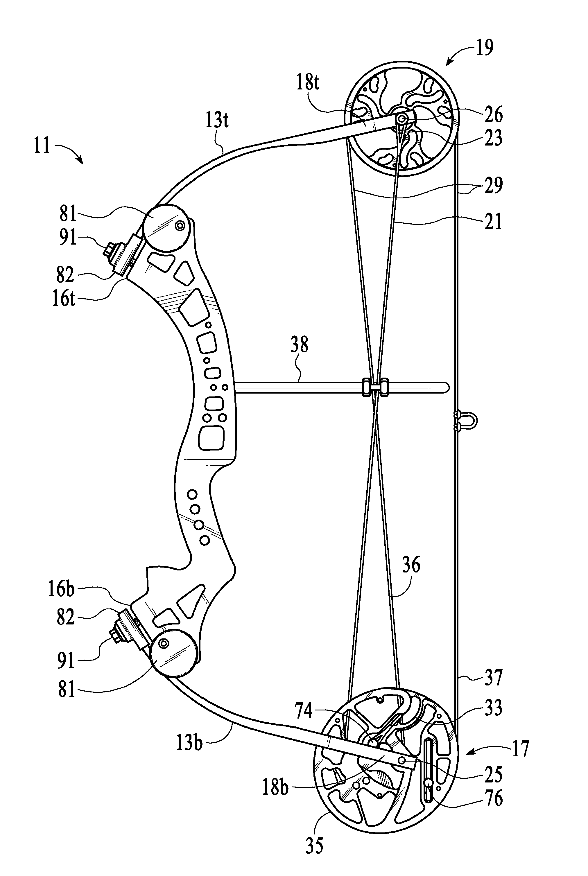
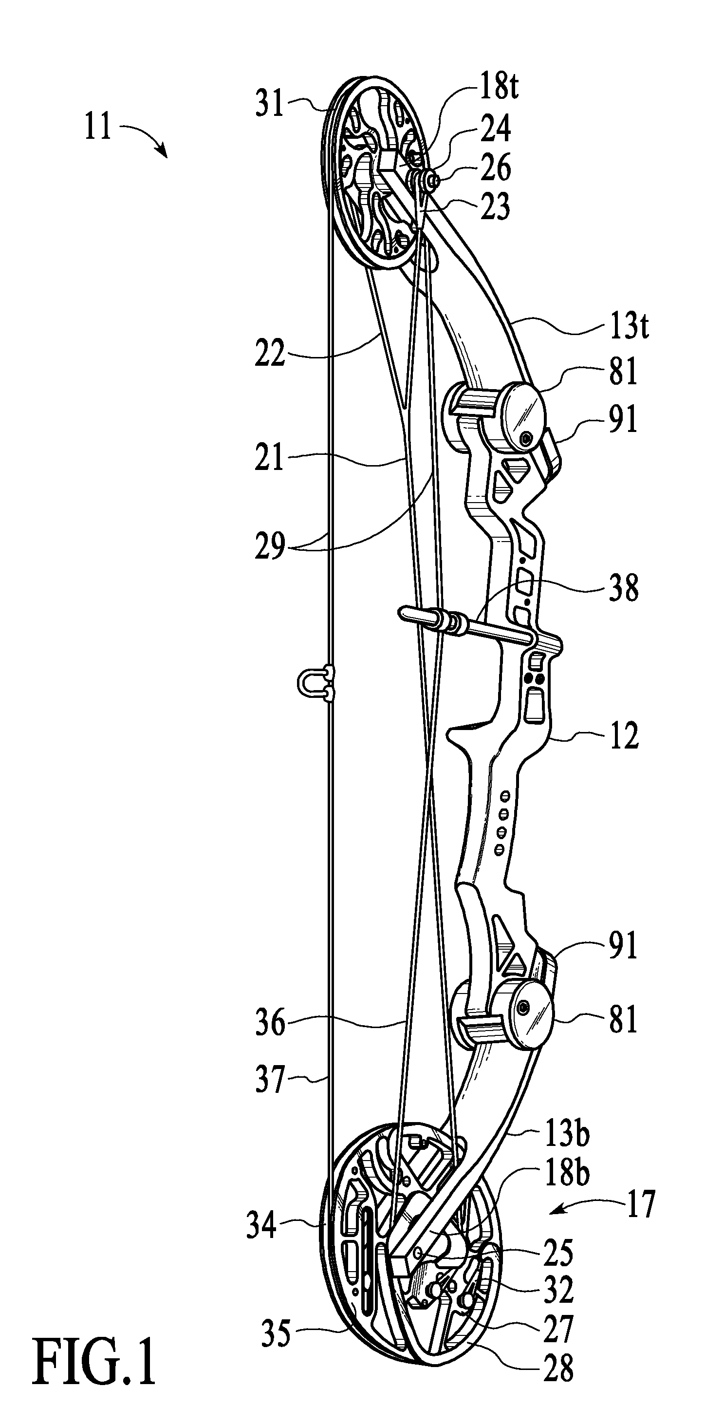
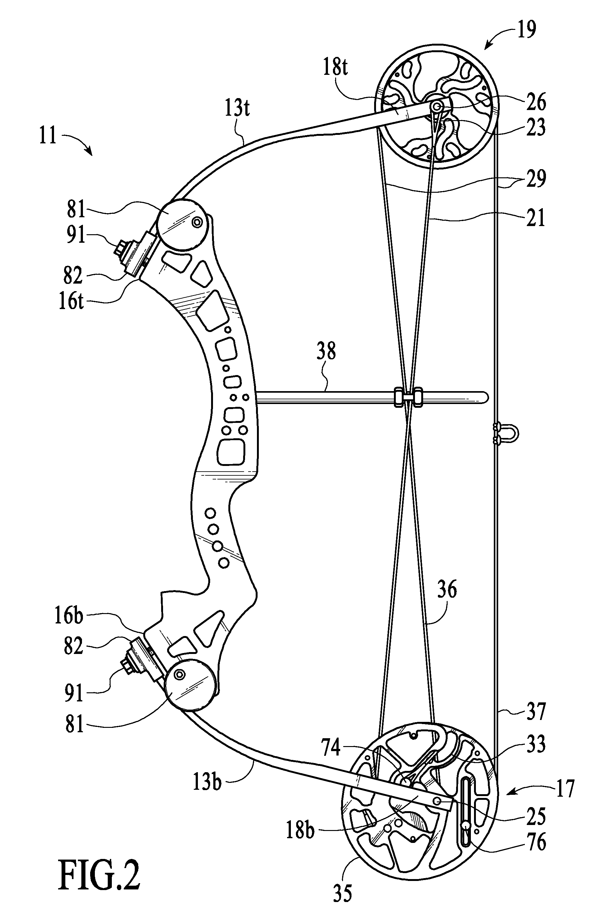
[0041]FIGS. 1-3, 5c, 14&15 each show a strung, single-cam compound bow 11 at the brace position that includes a rigid, structural riser body 12 with a pair of matched resilient bow limbs 13t &13b with slotted anchor ends 14 (FIG. 12) respectively anchored at top and bottom, bow-limb mount faces 16t &16b (FIG. 13a &13b) of the riser body 12. A dual cam power pulley 17 (see FIGS. 3, 4, 9, 10a, &10b) is supported by an axle 25 for rotation within a yoke 18b at the extending distal end of the bottom bow limb 13b. A conventional idler / control (radial) pulley 19 is supported by an axle 26 for rotation within a yoke 18t at the distal of the top bow limb 13t. A conventional power cable 21 and a drawstring cable 29 of the bow 11 are tensioned at an initial brace (undrawn) state by flexure of the anchored bow-limbs 13t &13b. A pair of end loops 23 at the yoke end 22 of the power cable 21 are conventionally anchored around the extending ends 24 of the idler / control pulley axle 26. The cam end ...


PUM


Abstract

Improved compound archery bow features a cable guard that separates the crossing inside cable segments allowing the intersection locus of the crossing cable inside segments to freely glide through the guard as the bow is drawn and released, a dual cam power pulley having a power lobe cam presenting a power cable race spiraling outward on a side face of an elliptical draw lobe cam presenting a draw-lobe cable race where the power cable winds as the inside drawstring cable segment unwinds from around the power cable race of the power lobe cam, and the outside drawstring cable segment unwinds from and winds-up around the draw-lobe cable race of the elliptical draw lobe cam as the bow is drawn and released, and bow-limb mounting and limb-pod structures at the respective ends of the bow riser for anchoring, aligning and supporting extending bow limbs for flexure.

Description

RELATED APPLICATIONS[0001]This Application is a continuation-in-part of U.S. Design Patent Application Ser. No. 29 / 332,508 filed by the applicants 18 Feb. 2009 and claims all applicable benefits under 35 U.S.C. §120. This Application also claims all applicable benefits under 35 U.S.C. §119(e) relative to U.S. Provisional Patent Application Ser. No. 61 / 175,419filed on behalf of the Applicant William C. Dahl II on 4 May 2009 entitled “SUPER CABLE GUARD GLIDE SLIDER FOR COMPOUND Bows. Both U.S. Design Patent Application Ser. No. 29 / 332,508 and U.S. Provisional Patent Application Ser. No. 61 / 175,419 are incorporated by reference in their entirety into this application.BACKGROUND OF THE INVENTION[0002]1. Field of the Invention[0003]The inventions relate to features improving performance of compound archery bows, namely:[0004](i) cable guards that separate the intersecting crossing locus of the inside cables, allowing the cables to freely glide through the guard as the bow is drawn and re...

Claims


Application Information

Patent Timeline
Patent Type & Authority Applications(United States)
IPC IPC(8): F41B5/10F41B5/14
CPCF41B5/10F41B5/1415F41B5/14F41B5/105F41B5/0094
Inventor DAHL, II, WILLIAM C.PELLEGRINI, MARIOMUIRHEAD, JEFFREY
Owner TNT ARCHERY
Learn More