Photovoltaic system with battery and reserve power plant

Inactive Publication Date: 2010-10-21
ADENSIS
View PDF6 Cites 21 Cited by
  • Summary
  • Abstract
  • Description
  • Claims
  • Application Information

AI Technical Summary

Benefits of technology

[0017]When both DC motors approach a predetermined upper temperature, the reserve power plant must be switched in. The reserve power plant can be operated at an output voltage of 400 V, but also at the voltage of the PV system of about 700 V, in which case the currents are again close to the nominal current of the DC machines. Ideally, the output voltage of the reserve power plant is regulated to match the voltage of the photovoltaic system. In this way, the battery can then be replaced, after short-time use, by the reserve power plant as supplier of power for a lo

Problems solved by technology

With this measure, the power deficiency can be supplied from the battery when

Method used


Image

  • Photovoltaic system with battery and reserve power plant
  • Photovoltaic system with battery and reserve power plant
  • Photovoltaic system with battery and reserve power plant

Examples


Embodiment Construction

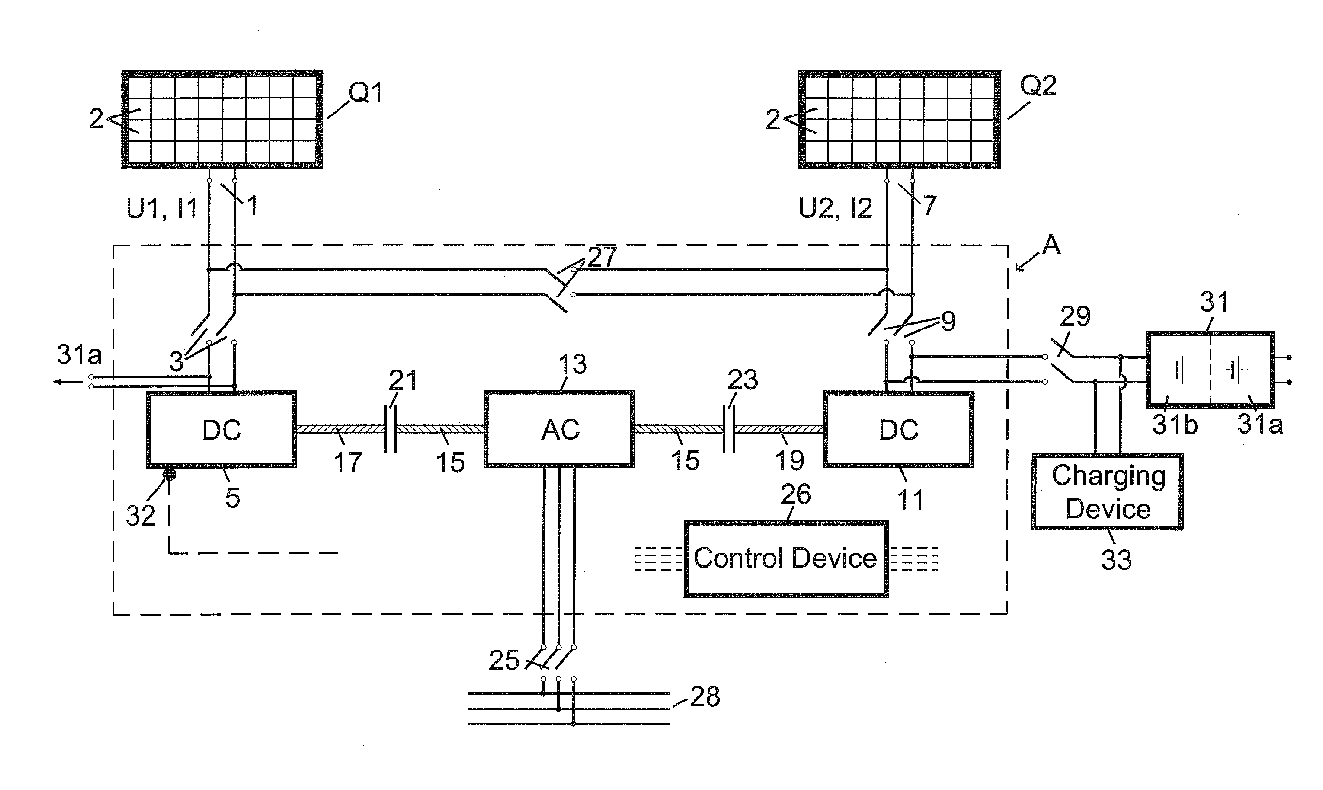
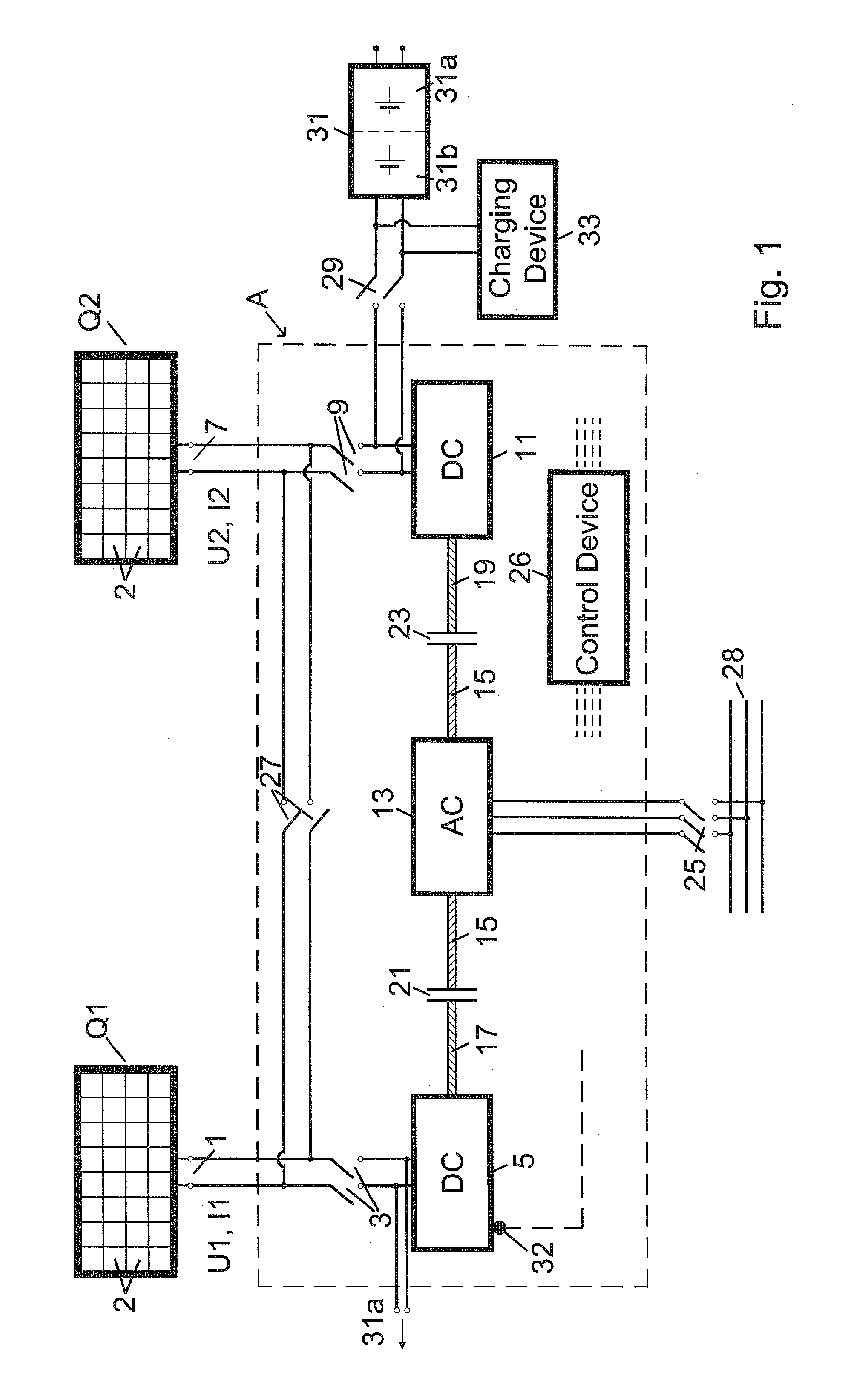
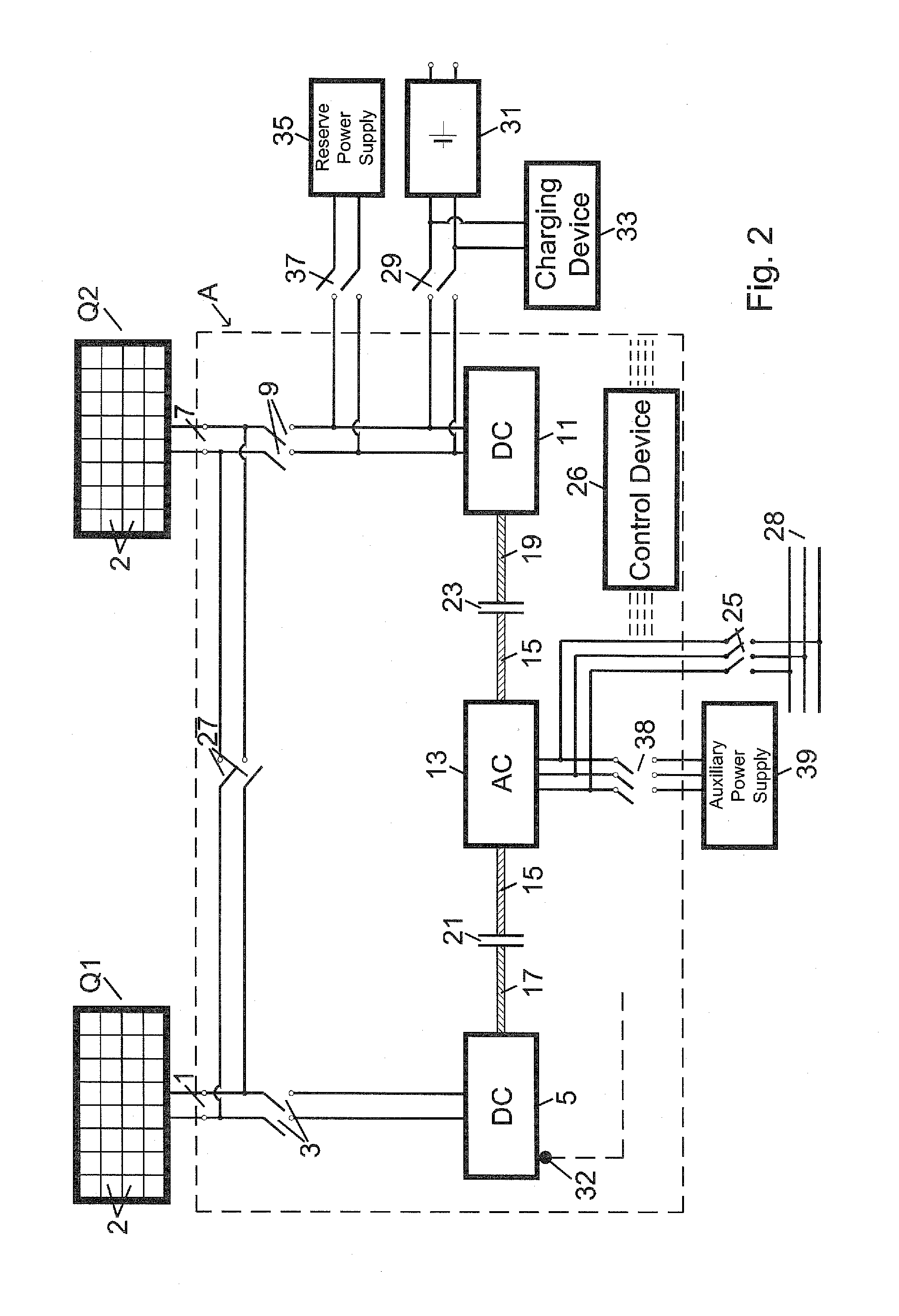
[0024]Throughout all the figures, same or corresponding elements may generally be indicated by same reference numerals. These depicted embodiments are to be understood as illustrative of the invention and not as limiting in any way. It should also be understood that the figures are not necessarily to scale and that the embodiments are sometimes illustrated by graphic symbols, phantom lines, diagrammatic representations and fragmentary views. In certain instances, details which are not necessary for an understanding of the present invention or which render other details difficult to perceive may have been omitted.

[0025]Turning now to the drawing, and in particular to FIG. 1, there is shown a photovoltaic system with a first group Q1 of photovoltaic modules 2 as a first energy source, which has an first output terminal pair 1 supplying a DC voltage U and a DC current I. The output terminal pair 1 is connected to a first externally-excited DC motor 5 by way of a first switch 3 for powe...


PUM


Abstract

A method for operating a photovoltaic system with a plurality of photovoltaic modules and with a DC motor connected to the photovoltaic modules is proposed. The motor shaft of the DC motor is coupled to a generator shaft of a three-phase generator, wherein the three-phase generator can be connected to a power grid. The motor shaft of a second DC motor can also be connected with the generator shaft, and the electric energy produced by the photovoltaic modules is initially only used for driving a single DC motor and is during the subsequent operation divided between those DC motors. A battery is provided which can be connected with the second DC motor instead of the PV system by changing the excitation of the second DC motor such that it's motor voltage corresponds to the open-circuit voltage of the battery.

Description

CROSS-REFERENCES TO RELATED APPLICATIONS[0001]This application claims the priority of German Patent Application, Serial No. 10 2009 018 240.3, filed Apr. 21, 2009, pursuant to 35 U.S.C. 119(a)-(d), the content of which is incorporated herein by reference in its entirety as if fully set forth herein.BACKGROUND OF THE INVENTION[0002]The invention relates to a method and a device for operating a photovoltaic (PV) system having a plurality of photovoltaic modules and a first and a second DC motor connected to the photovoltaic modules, wherein the DC motors are or can be coupled to a three-phase generator, wherein the three-phase generator can be connected to a power grid, and wherein the electric energy supplied by a photovoltaic modules can be distributed to the to DC motors in any selected arrangement.[0003]The following discussion of related art is provided to assist the reader in understanding the advantages of the invention, and is not to be construed as an admission that this rela...

Claims


Application Information

Patent Timeline
IPC IPC(8): H02J7/34
CPCY02E10/566H02J7/35Y02E10/56
Inventor BECK, BERNHARD
Owner ADENSIS
Why Eureka
Try Eureka