Maximum Power Point Tracking Charge Controller with Coupled Inductor Multi-phase Converter

a charge controller and inductance multi-phase technology, applied in secondary cell servicing/maintenance, process and machine control, instruments, etc., can solve the problems of non-mppt charge controllers artificially limit power production to a sub-optimal level, under-utilization of the maximum power output of pv arrays, and significant power production

Active Publication Date: 2010-10-21
MORNINGSTAR CORP
View PDF7 Cites 34 Cited by
  • Summary
  • Abstract
  • Description
  • Claims
  • Application Information

AI Technical Summary

Problems solved by technology

Usually there is a mismatch between the output voltage of the PV array and the voltage required to charge the battery bank that results in under-utilization of the maximum power output from the PV array.
The reason for the mismatch is that most PV modules are rated to produce a nominal 12V under standard test conditions but, because they are designed for worse than standard test conditions, in actual fact they produce significantly more power.
Hence, non-MPPT charge controllers artificially limit power production to a sub-optimal level by constraining the PV array from operating at maximum output power.
In addition, lower battery voltage, as in the case of a highly discharged battery, will result in a greater charge current increase.
The use of capacitors to filter input and output ripples has various disadvantages including added cost and slowing down the system control bandwidth that manages transients.
In the area of MPPT charge controllers for PV systems, various obstacles have stood in the way of a coupled inductor multi-phase buck converter including the increased EMI associated with a coupled inductor, the added difficulty involved in controlling the buck converter as the phases interact, and the loss of stability in simple controller loops.

Method used


Image

  • Maximum Power Point Tracking Charge Controller with Coupled Inductor Multi-phase Converter
  • Maximum Power Point Tracking Charge Controller with Coupled Inductor Multi-phase Converter
  • Maximum Power Point Tracking Charge Controller with Coupled Inductor Multi-phase Converter

Examples


Embodiment Construction

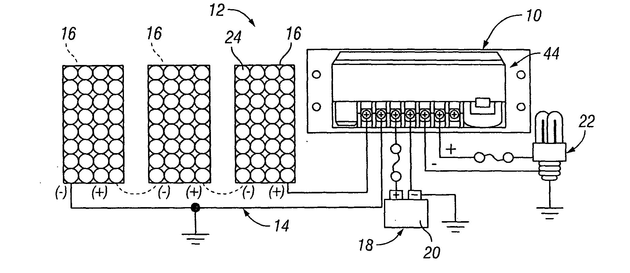
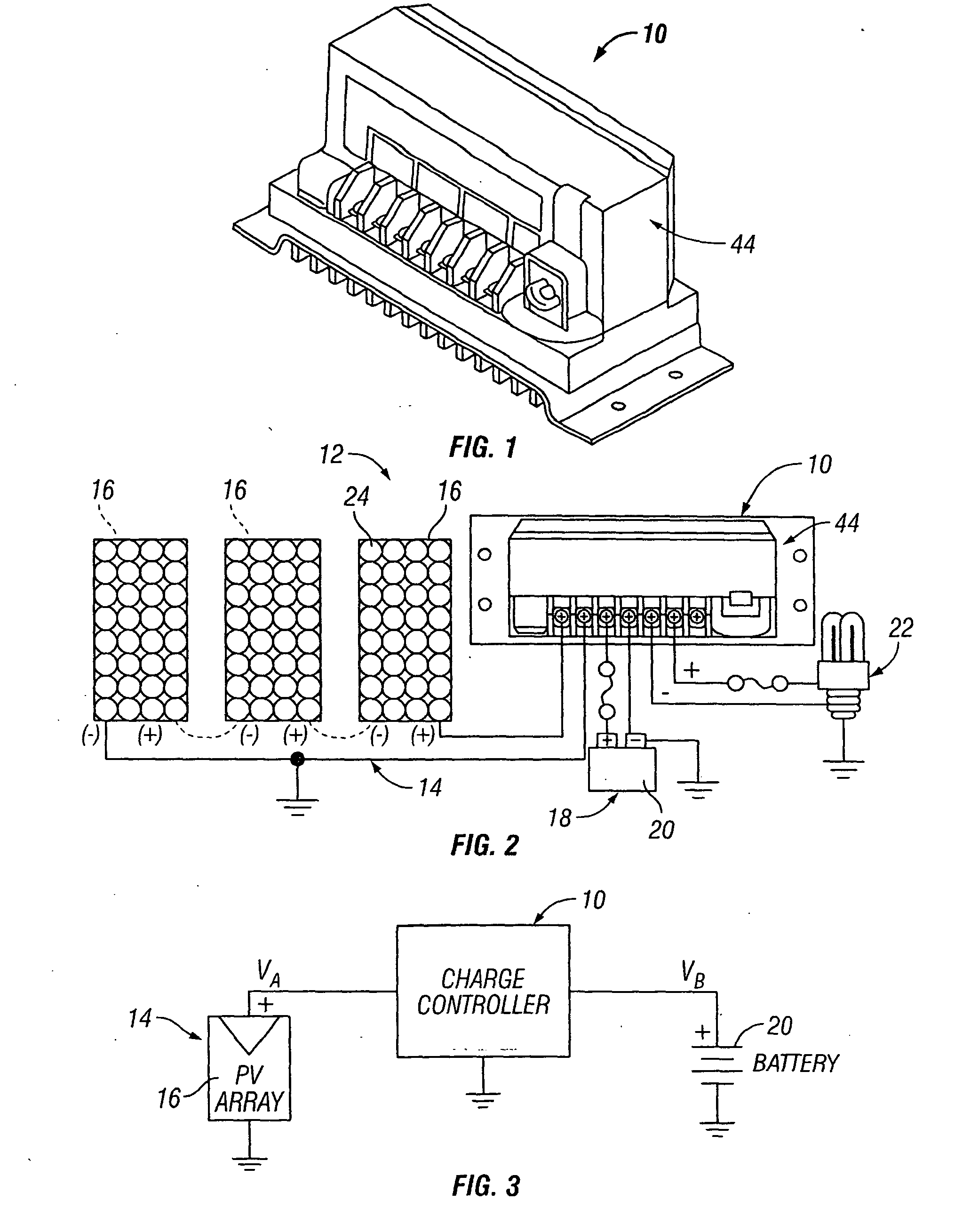
[0035]A maximum power point tracking (MPPT) charge controller 10 having a coupled inductor multi-phase converter is illustrated in FIGS. 1 and 2, the MPPT charge controller 10 being shown in FIG. 2 incorporated in a photovoltaic (PV) system 12. The PV system 12 comprises a photovoltaic (PV) array 14 including one or more photovoltaic (PV) modules or panels 16, a battery bank 18 including one or more batteries 20, and the MPPT charge controller 10 electrically connected to the array 14 and to the battery bank 18. The MPPT charge controller 10 is shown in FIG. 2 with a load output connection of the controller electrically connected to a load 22 that is to be powered by the PV system 12. The load output connection on the MPPT charge controller 10 functions to deliver battery voltage to the load 22. Typical loads 22 include lights, pumps, motors, DC appliances, and electronic devices. The load output connection of the MPPT charge controller 10 can be electrically connected to a load dis...


PUM


Abstract

A maximum power point tracking (MPPT) charge controller for photovoltaic (PV) systems employs a maximum power point tracking algorithm for tracking the maximum power point voltage of a PV array at which the PV array produces maximum power voltage, and a buck converter for converting the maximum power voltage to the voltage required to charge one or more batteries. The buck converter includes multiple buck converter phase configurations phase shifted from one another. Each of the buck converter phase configurations has a phase inductor, and the phase inductors are combined on a single core to form a coupled inductor. One of the buck converter phase configurations is intentionally temporarily shut down when the output power is low. A first switch or a second switch of the buck converter phase configuration that is intentionally temporarily shut down is turned on to conduct electrical current when predetermined conditions are satisfied. A method of controlling battery charging in a photovoltaic system involves operating a coupled inductor multi-phase buck converter of a charge controller so that one of the buck converter phase configurations is intentionally temporarily shut down when the power output is below a predetermined value.

Description

BACKGROUND OF THE INVENTION[0001]1. Field of the Invention[0002]The present invention pertains generally to photovoltaic system charge controllers and, more particularly, to photovoltaic system charge controllers that employ maximum power point tracking.[0003]2. Brief Discussion of the Related Art[0004]Photovoltaic (PV) systems that produce electricity from solar energy have established themselves as a successful and reliable option for electrical power generation. Photovoltaic systems have continually been gaining in popularity as the cost of such systems has been reduced, as the cost of utility-supplied power has escalated, and as greater attention has been paid to the need for renewable, alternative energy sources. Basically, a photovoltaic system includes a photovoltaic (PV) array made up of one or more PV panels or modules composed of photovoltaic cells capable of converting solar energy into electrical energy, a battery bank made up of one or more batteries for storing the ele...

Claims


Application Information

Patent Timeline
Patent Type & Authority Applications(United States)
IPC IPC(8): H02J7/35G05F1/618
CPCG05F1/67Y02E10/58H02M3/1584Y02E10/56
Inventor DUBOVSKY, STEPHEN
Owner MORNINGSTAR CORP
Why Eureka
Try Eureka