Magnetic Manual User Interface Devices

a user interface device and magnetic technology, applied in the direction of mechanical control devices, manual control with single controlling member, instruments, etc., can solve the problem that qwerty keyboards are often not the best user interface devices for a given application

Inactive Publication Date: 2010-10-21
SEEKTECH
View PDF42 Cites 122 Cited by
  • Summary
  • Abstract
  • Description
  • Claims
  • Application Information

AI Technical Summary

Problems solved by technology

The QWERTY keyboard is often not the best...

Method used


Image

  • Magnetic Manual User Interface Devices
  • Magnetic Manual User Interface Devices
  • Magnetic Manual User Interface Devices

Examples


first embodiment

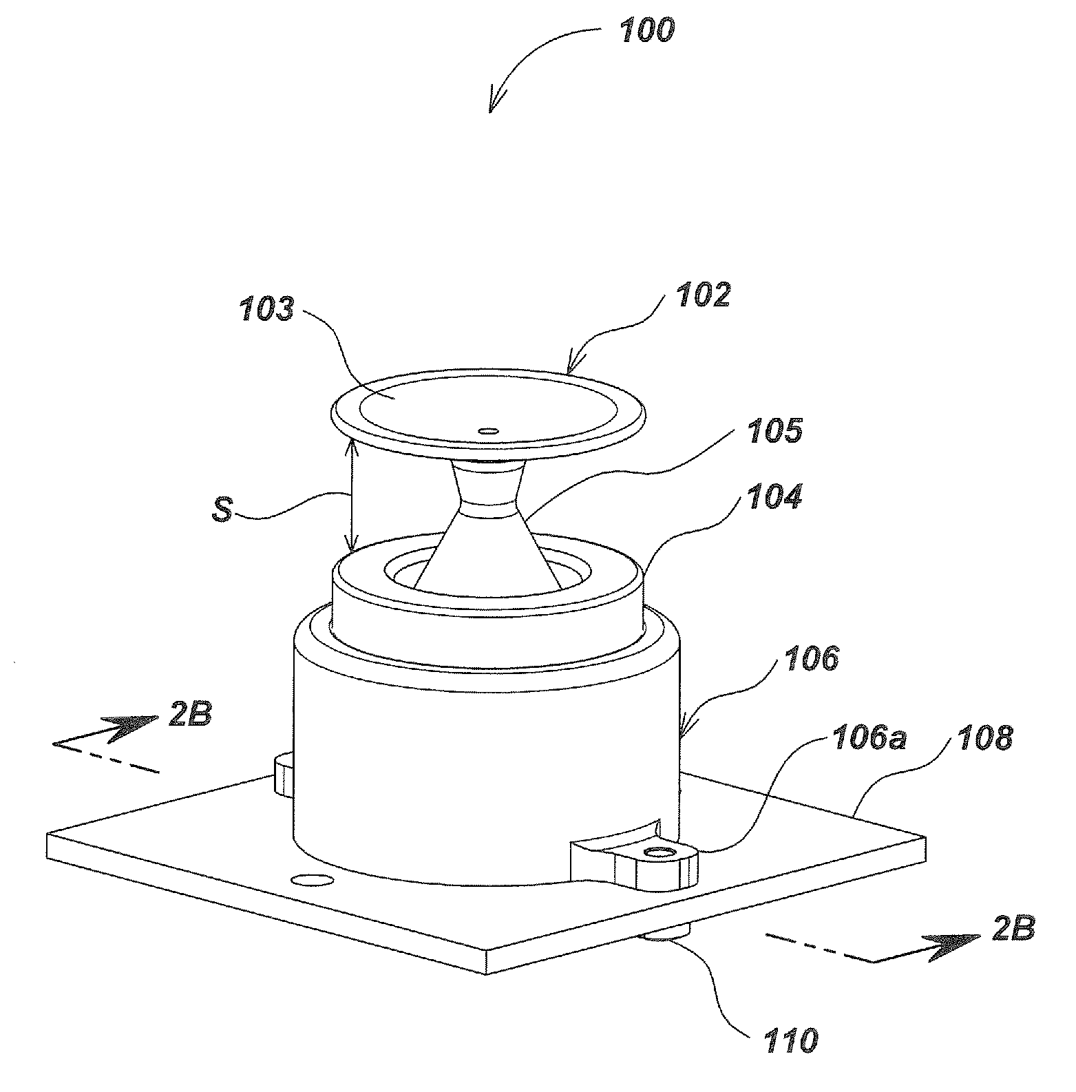
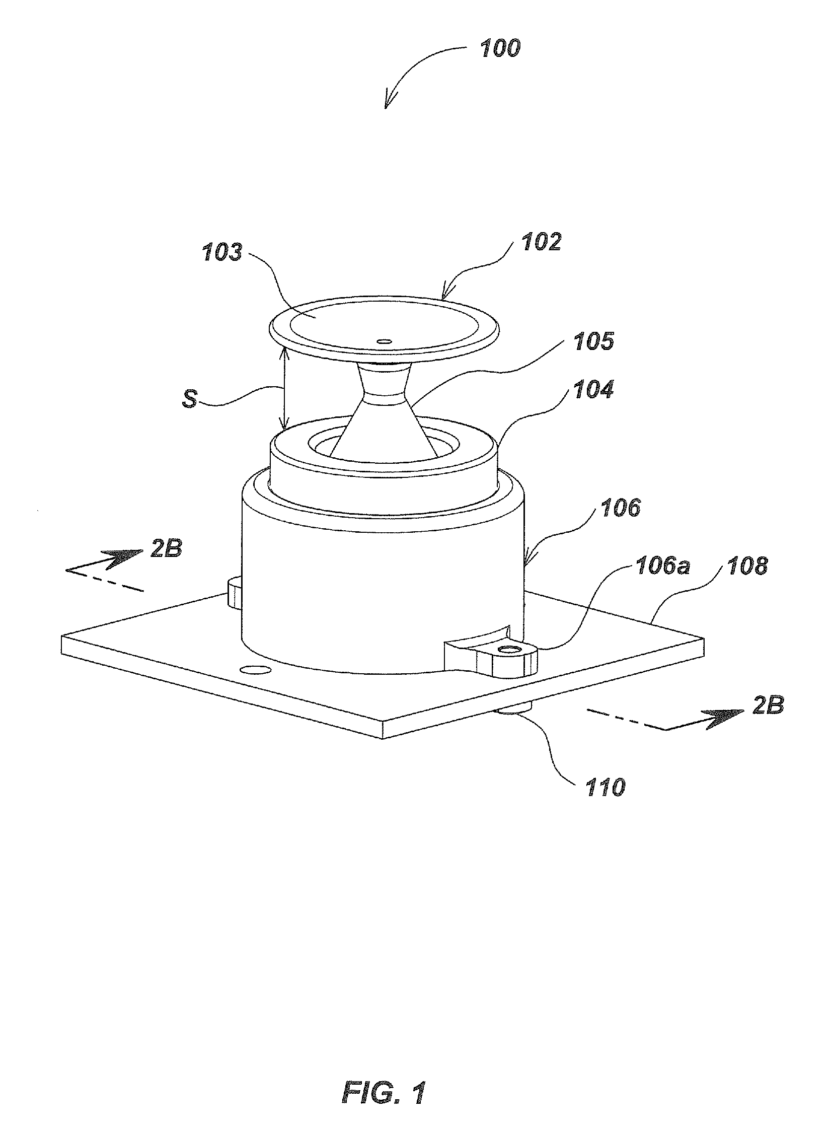
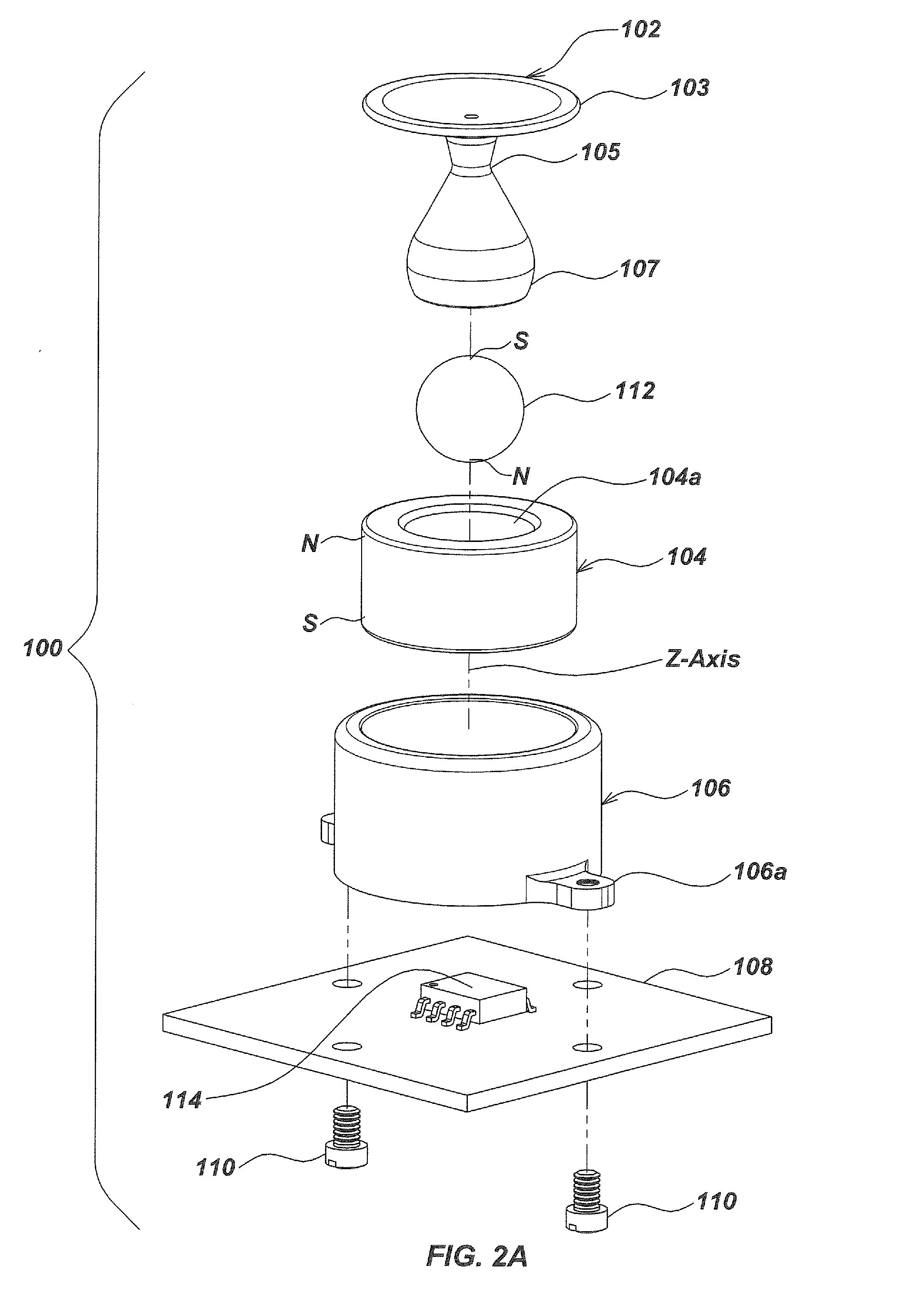
[0117]Referring to FIG. 1, a magnetic manual user interface device 100 has a ball and socket joystick configuration that includes a manual actuator 102 comprising an integrally molded hour glass-shaped plastic actuator shaft 105, a paddle 103 and a magnet cup 107 (FIG. 2A). The paddle 103 is disk-shaped and extends horizontally from the upper end of the actuator shaft 105. An exemplary diameter for the paddle 103 is one inch (2.54 centimeters). The manual actuator 102 is rigidly connected to a spherical magnet 112 (FIG. 2A) which is suspended concentrically within a central cylindrical bore 104a (FIG. 2A) of an annular magnet 104, mounted in a rigid cylindrical plastic shell 106.

[0118]Referring to FIG. 2A, the North-South (N-S) magnetic axis of the spherical magnet 112 is aligned with the vertical axis of the actuator shaft 105. The magnet cup 107 fits over the spherical magnet 112 and is prevented from slipping relative to the spherical magnet 112 by snap-over force, adhesive bondi...

embodiment 100

[0128]Additional fixed or variable bias magnets (not illustrated in FIGS. 1-2B) may be added to the embodiment 100 to modify magnetic field responses, counteract magnetic saturation, or the like. A plurality of the magnetic sensors 114 may be used to refine or configure the detection of events in keeping with the data requirements of a given application. Different forms of the annular magnet 104 and spherical magnet 112 may be used. In a converse configuration the spherical magnet 112 may be fixed while the annular magnet 104 is movable around it.

[0129]FIGS. 4 and 5 illustrate a magnetic manual user interface device 450 that includes a bias magnet 452 that is attached to the bottom of a spherical magnet 112. A magnetic sensor 114 is protected by a sealing barrier 454. The bias magnet 452 has a disk-shape and a diameter smaller than that of the spherical magnet 112. The bias magnet 452 is attached to the lower side of the spherical magnet 112 in an off-center position, i.e. spaced fr...


PUM


Abstract

Various finger tip controlled manual interface devices that can be used as inputs to personal computers, electromechanical systems and video game consoles utilize concentrically arranged magnets. The polarities of the magnets are oriented to provide restoration forces on a one of the magnets to bias it toward a neutral position. A magnetic sensor including a plurality of sensing elements such as Hall effect devices generates output signals representative of direction and amount of movement of the magnet that is biased to the neutral position.

Description

CROSS-REFERENCE TO RELATED APPLICATIONS[0001]The present application claims priority based on U.S. Provisional Patent Application No. 61 / 169,656, filed on 15 Apr. 2009, entitled Magnetic Ball and Ring User Interface Device, U.S. Provisional Patent Application No. 61 / 235,668 filed on Aug. 20, 2009 entitled Magnetic Ball and Ring User Interface Device, and U.S. Provisional Application No. 61 / 236,034 filed on Aug. 21, 2009 entitled Enhanced Magnetic User Interface Devices.FIELD OF THE INVENTION[0002]The present invention relates to manual input devices, such as joysticks, that function as user interfaces to electronic computing devices.BACKGROUND OF THE INVENTION[0003]There are many electronic computing systems, such as personal computers and video game consoles, that have interface circuitry and / or interface software designed to function with a manual user input device that can be readily manipulated by a user to input commands, move a cursor, select an icon, move a player in a video ...

Claims


Application Information

Patent Timeline
IPC IPC(8): G06F3/033
CPCG05G5/05G05G9/047G06F3/0338G05G2009/04755G06F3/016G05G2009/04707
Inventor OLSSON, MARK S.MEREWETHER, RAYCANEPA, LONI M.WARREN, ALEXANDER L.JESSUP, AMOS H.MARTIN, MICHAEL J.JEMMOTT, GEORGE L.
Owner SEEKTECH
Why Eureka
Try Eureka