

LED illuminating device
a technology led lamps, which is applied in the direction of lighting support devices, semiconductor/solid-state device details, printers, etc., can solve the problems of affecting the brightness, lifespan, reliability of led illuminating devices, and conventional heat dissipation devices, such as heat sinks, cannot meet the requirements of heat dissipation
- Summary
- Abstract
- Description
- Claims
- Application Information
AI Technical Summary
Benefits of technology
Problems solved by technology
Method used
Image

Examples
first embodiment
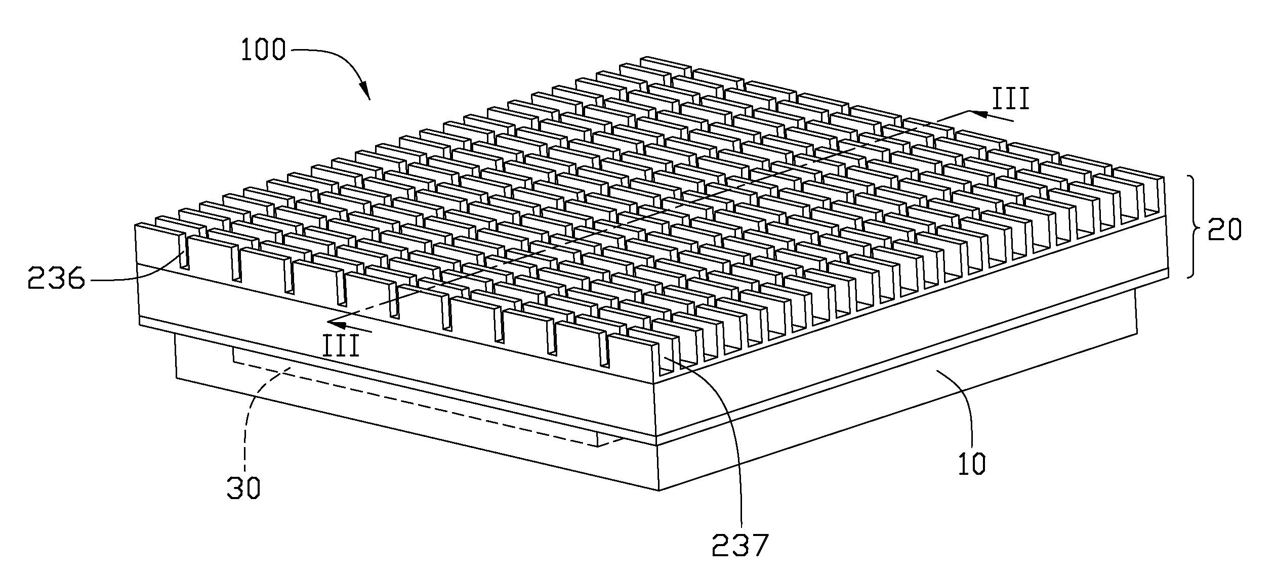
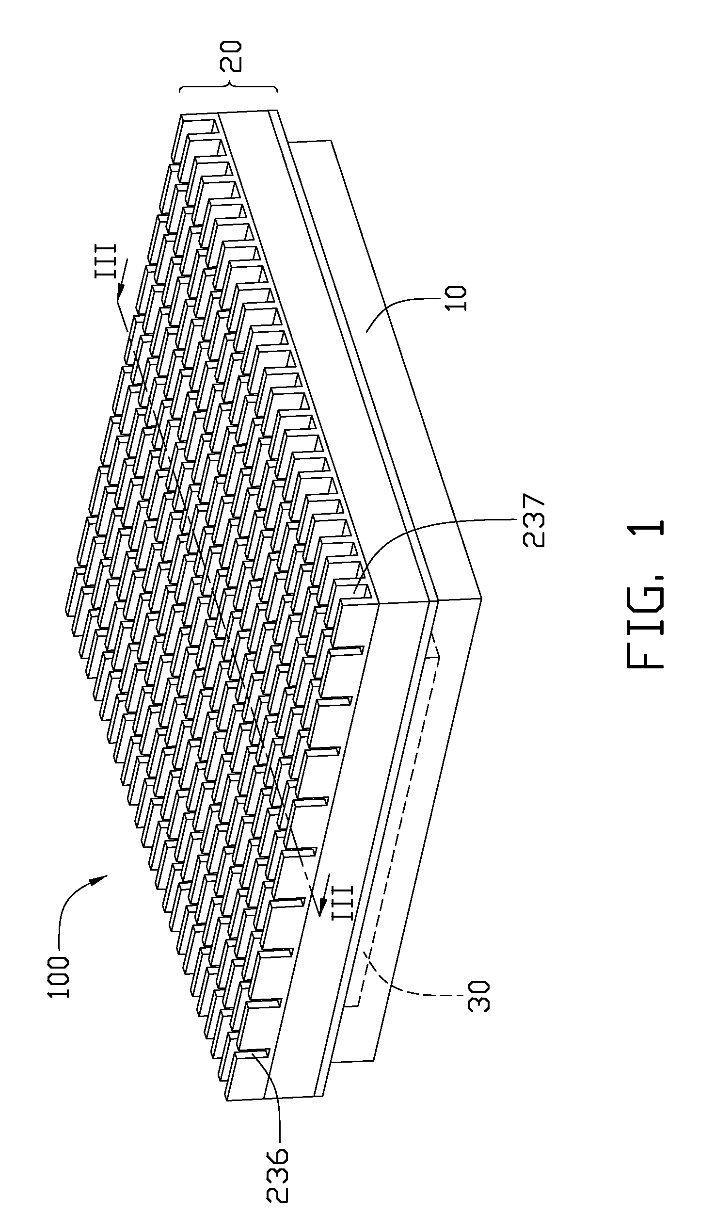
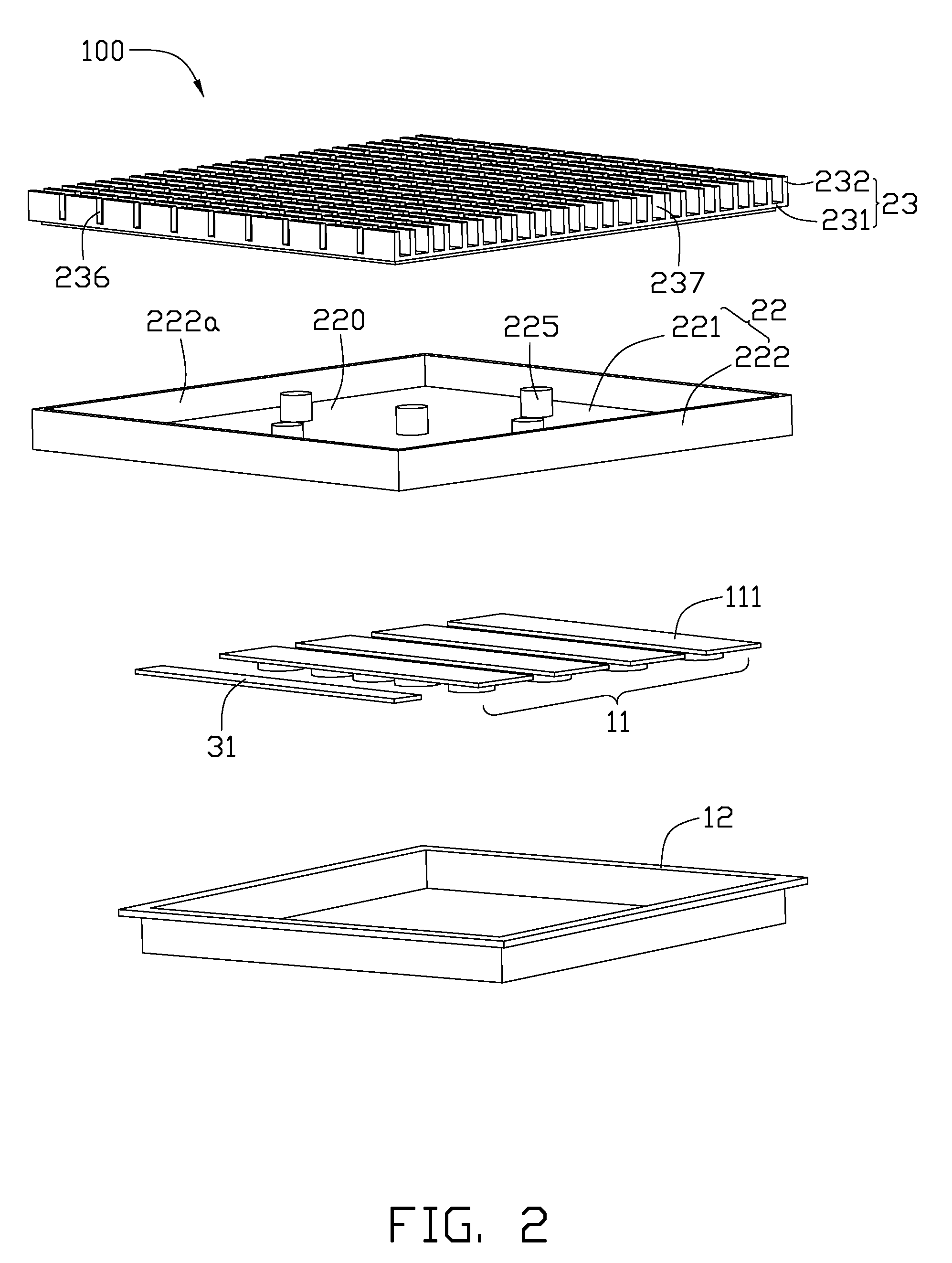
[0018]Referring to FIGS. 1-2, an LED illuminating device 100 includes an optical module 10, a heat dissipation device 20 arranged above the optical module 10, and an electrical module 30 electrically connected with the optical module 10.
[0019]Referring also the FIG. 3, the heat dissipation device 20 includes a housing 22 and a heat sink 23 mounted on the housing 22. The housing 22 is made of a material with an excellent heat conductivity such as copper or aluminum. The housing 22 includes a bottom plate 221 and a closed sidewall 222 extending vertically and upwardly from an outer periphery of the bottom plate 221. The bottom plate 221 is substantially rectangular, and has an evaporating surface 223 at a top side thereof facing the heat sink 23 and an opposite heat absorbing surface 224 at a bottom side thereof. The housing 22 defines a recess 220 therein. The recess 220 is surrounded by the sidewall 222 and above the bottom plate 221. A plurality of supporting members are provided ...
second embodiment
[0028]Referring to FIG. 4, a heat dissipation device 20a of an LED illuminating device is illustrated. The heat dissipation device 20a includes a U-shaped housing 22a at a bottom side thereof and a heat sink 23a mounted on the housing 22a. The housing 22a includes a rectangular bottom plate 221a and two parallel first side plates 222a formed on two opposite sides of the bottom plate 221a. The two first side plates 222a extend vertically and upwardly from front and rear sides of the bottom plate 221a towards the heat sink 23a. Two engaging grooves 227 are defined in an evaporating surface 223a of the bottom plate 221a and located at the other two opposite sides (i.e., left and right sides) of the bottom plate 221a. Two opposite ends of each engaging groove 227 extend upwardly in inner surfaces of the two first side plates 222a to top ends of the two first side plates 222a. The housing 22a can be integrally formed as a single piece by extrusion or pressing.
[0029]The heat sink 23a inc...
third embodiment
[0031]Referring to FIGS. 5-6, an LED illuminating device 100b is illustrated. Except the following differences, the LED illuminating device 100b of the present embodiment is essentially the same as the LED illuminating device 100 of the previous embodiment. In the present embodiment, two cooling fans 26 and a top cover 27 are provided above the heat sink 23. The cooling fans 26 are arranged on top ends of the fins 232 of the heat sink 23. The top cover 27 includes a rectangular top plate 273 and a peripheral wall 272 extending downwardly from an outer periphery of the top plate 273 towards the heat sink 23. A plurality of air holes 271 are defined in the peripheral wall 272 of the top cover 27. The top cover 27 is mounted on the heat sink 23 and covers the fans 26 and the fins 232 of the heat sink 23 therein.
[0032]When the cooling fans 26 operate, the cooling fans 26 inhale air into the top cover 27 via some of the air holes 271, which are located corresponding to the communicating...
PUM
 Abstract
Description
Claims
Application Information