Clock face keyboard

a clock face and keyboard technology, applied in the field of electronic instruments with data entry keyboards, can solve the problems of inconvenient placement of full alphanumeric keyboards, cumbersome frequent use, and inconvenient use of computer interface devices currently used in home or office, so as to minimize the number of strokes needed, minimize the number of strokes, and the effect of reducing the initial learning tim

Active Publication Date: 2010-10-21
MIN BYUNG KON
View PDF101 Cites 16 Cited by
  • Summary
  • Abstract
  • Description
  • Claims
  • Application Information

AI Technical Summary

Benefits of technology

[0021]An objective of the present invention is to provide the users of small hand held electronic devices, such as PC remote controls, mobile phones, personal digital assistants (PDAs), and game controls with a means of data entry that can be operated by one hand. An objective of the present invention is to incorporate substantially the functionality of a full size keyboard into such small devices.
[0022]An objective of the present invention is to provide the users with such small devices with full size keyboard functionality that is easy to learn and use.
[0023]An objective of the prese...

Problems solved by technology

It is recognized that most computer interface devices currently used in home or office are not suitable in a confined or remote environments.
This is acceptable only for occasional use, but is too cumbersome for frequent use.
For the aforementioned hand-held devices, however, the placement of any full alphanumeric keyboards, such as the standard QWERTY keyboards along with numeric keypads, is prohibitive because of space limitations.
Although the Jung patent solutions are quite effective on both problems, one of the drawbacks of Jung's solutions is the lack of familiarity of the key layout to most people.
The mini QWERTY keyboard adds substantially to the size and weight of the mobile phones, a ...

Method used


Image

  • Clock face keyboard
  • Clock face keyboard
  • Clock face keyboard

Examples


embodiment 101

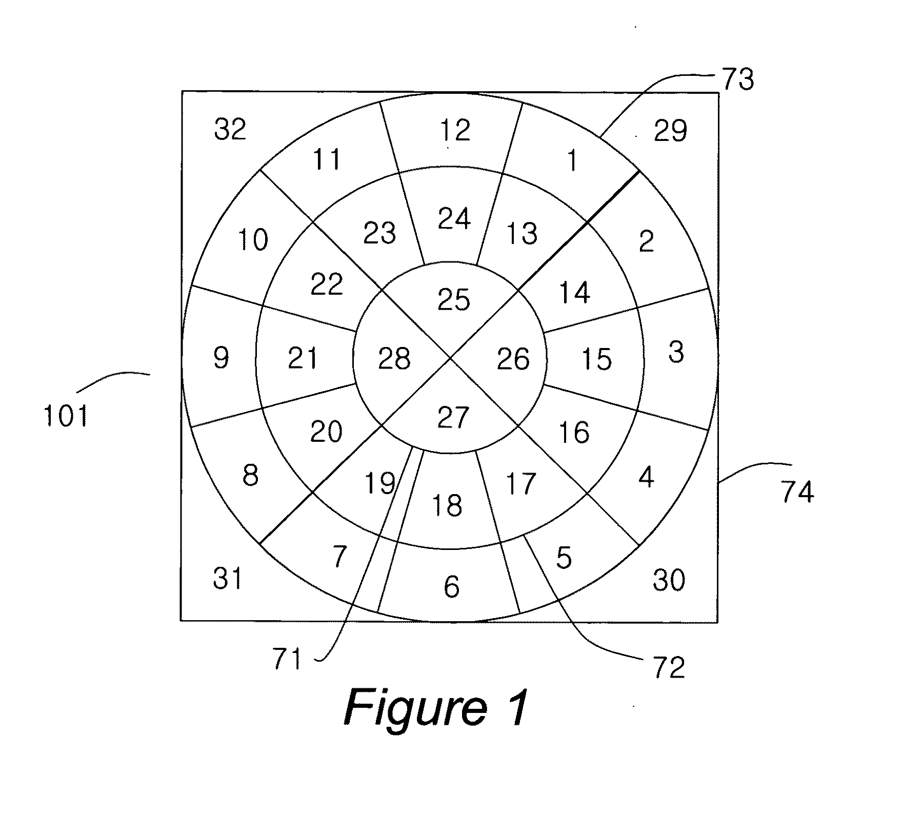
[0057]In the embodiment 101 of FIG. 1, twelve keys numbered 1 to 12 are located on the inner circle within a virtual inner annulus bounded by the concentric virtual circles 71 and 72. Twelve keys numbered 13-24 are located on the outer circle within a virtual outer annulus bounded by the concentric virtual circles 72 and 73. Four keys numbered 25-28 are located in the geometric center bounded by the concentric virtual circle 71. Finally additional four keys numbered 29-32 are located at the four corners within a tangential square 74 surrounding the outer concentric virtual circle 73.

[0058]In the embodiment 101 of FIG. 1, the key areas 1-28 are sized to have substantially an equal key area even though their shapes may not be identical. It can be easily shown that the key areas 1-28 are of an equal key area if the ratio of the radii of the concentric virtual circles 71, 72, and 73 are 1:2:√7 or approx. 1:2:2.65.

[0059]The generic clock face keyboard comprises double (inner and outer) c...

embodiment 32

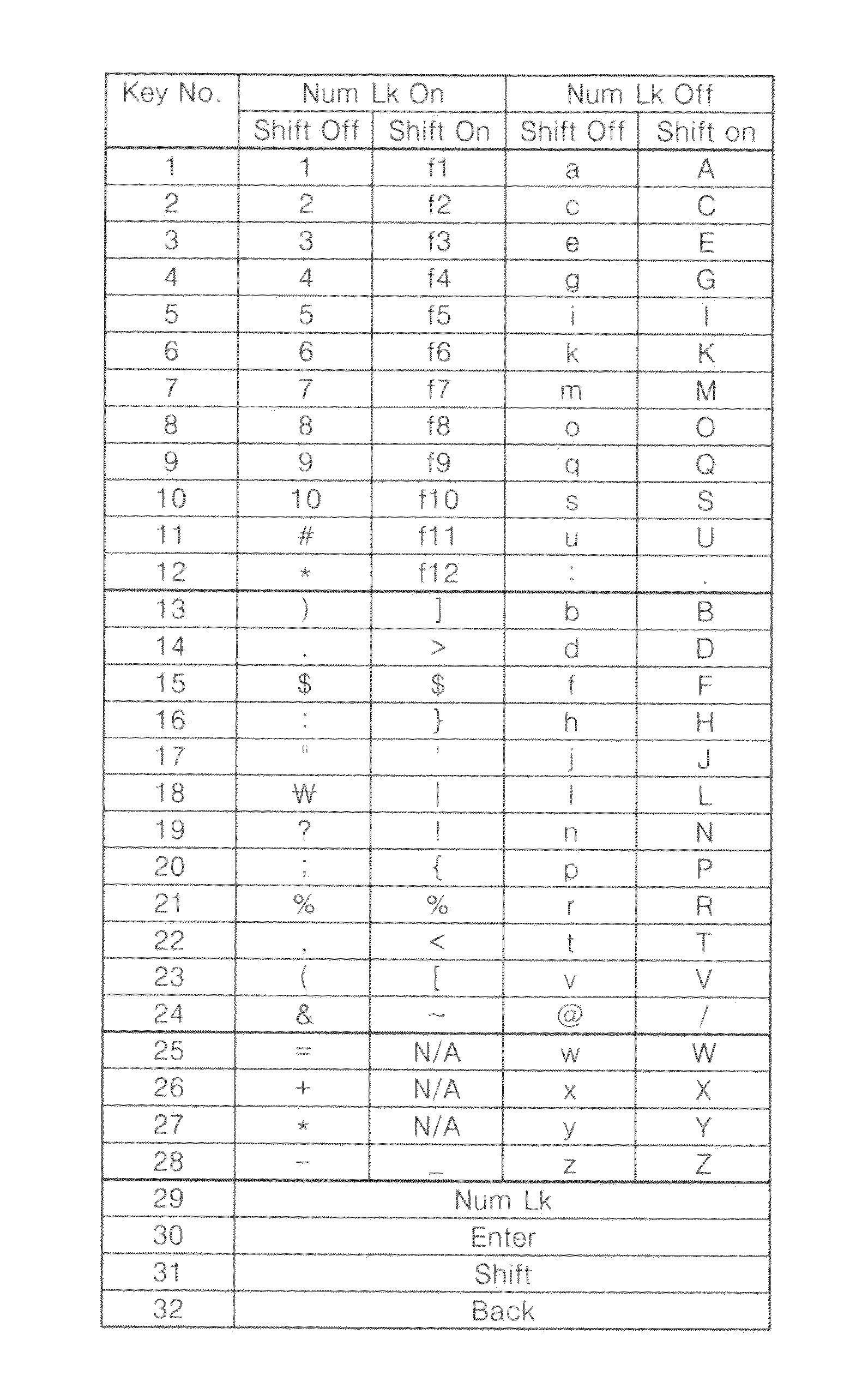
[0073]In the present embodiment, the 28 keys located on three concentric circles (e.g., the inner and outer concentric circles and the center circle) are used as alphanumeric keys and the four corner keys are used as selected control keys that are frequently used, including number lock key 29, enter key 30, shift key 31, and back space key 32. It is easily envisioned that these four corner keys 29-32 may be assigned additional alphanumeric functions instead, in which case, additional keys may be placed outside the tangential square to assign the same control functions. Although in the present embodiment 32 keys are shown and additional keys are not shown, such additions of additional keys outside the tangential square may be expected depending on the specific applications.

[0074]FIG. 3 lists the representative alphanumeric symbols that may be assigned to each of the 32 keys of the present keyboard arrangement (e.g., 12 keys on each of two concentric circles, four centrally located ke...


PUM


Abstract

An alphanumeric keyboard that is easy to learn, easy to use, and mountable on a handset for one-hand operation, comprises a virtual clock face having the center for the rotation of virtual hands, first set of twelve hourly radial positions, from one o'clock to twelve o'clock, surrounding the center, second set of twelve hourly radial positions, from one o'clock to twelve o'clock, surrounding the center and nearer to the center than the first set of twelve hourly radial positions, twenty four key areas, each key area being uniquely associated with one hourly radial position of the first and second sets, wherein each key area is substantially of 30 degree annular sector shape and contiguous to the adjacent key areas associated with the adjacent hourly radial positions, wherein all twenty four key areas are substantially of equal area, at least thirteen alphabetic keys placed at predetermined hourly radial positions of the first and second sets, and wherein each key has an indicia surface that is within the associated key area for being pressed by a finger. The associated radial direction or time may be marked on the key surface for visual or tactile differentiation.

Description

CROSS-REFERENCE TO RELATED APPLICATIONS[0001]This application is a continuation of the application “Circular Keyboard,” application Ser. No. 11 / 581,303 filed on Oct. 16, 2006, which claims the benefit of provisional applications “Circular Keyboard,” Application No. 60 / 726,932 filed on Oct. 15, 2005 and “Remote Input Device,” Application No. 60 / 777,069 filed on Feb. 27, 2006, all by the present inventor.FEDERALLY SPONSORED RESEARCH [0002]Not ApplicableSEQUENCE LISTING OF PROGRAM [0003]Not ApplicableBACKGROUND OF THE INVENTION[0004]1. Field Of The Invention[0005]The present invention relates to data entry keyboards for electronic instruments: more particularly to a space efficient, easy-to-use hand-held keyboard for small electronic devices, mobile phones, computers, Internet TVs, etc.[0006]2. Prior Art[0007]Broadband communications are becoming essential part of people's lives. Broadband Internet is becoming available even to airplane passengers for entertainment or work during fligh...

Claims


Application Information

Patent Timeline
IPC IPC(8): B41J5/00
CPCB41J5/10G06F1/1616G06F1/1626H04M1/23G06F3/0219G06F3/0234G06F1/1664
Inventor MIN, BYUNG KON
Owner MIN BYUNG KON
Why Eureka
Try Eureka