Traveling device and its control method

a technology of a travel device and a control method, applied in the direction of process and machine control, vehicle position/course/altitude control, instruments, etc., to achieve the effect of stable travel

Active Publication Date: 2010-10-21
TOYOTA JIDOSHA KK
View PDF3 Cites 7 Cited by
  • Summary
  • Abstract
  • Description
  • Claims
  • Application Information

AI Technical Summary

Benefits of technology

[0008]To achieve the above-described object, an exemplary aspect of the present invention is a traveling device including: ground touching detection means to detect a ground touching state in which a ground touching member touches a road surface; and control means to perform inversion control by controlling driving of a wheel; wherein when a ground touching state of the ground touching member is detected by the ground touching detection means, the control means suspends the inversion control. In accordance with this aspect, more stable traveling can be performed.

Problems solved by technology

Further, in this aspect, the control means may increase the gain value of the wheel drive control and suspend the inversion control as the ground touching member gets closer to the road surface.

Method used


Image

  • Traveling device and its control method
  • Traveling device and its control method
  • Traveling device and its control method

Examples


first exemplary embodiment

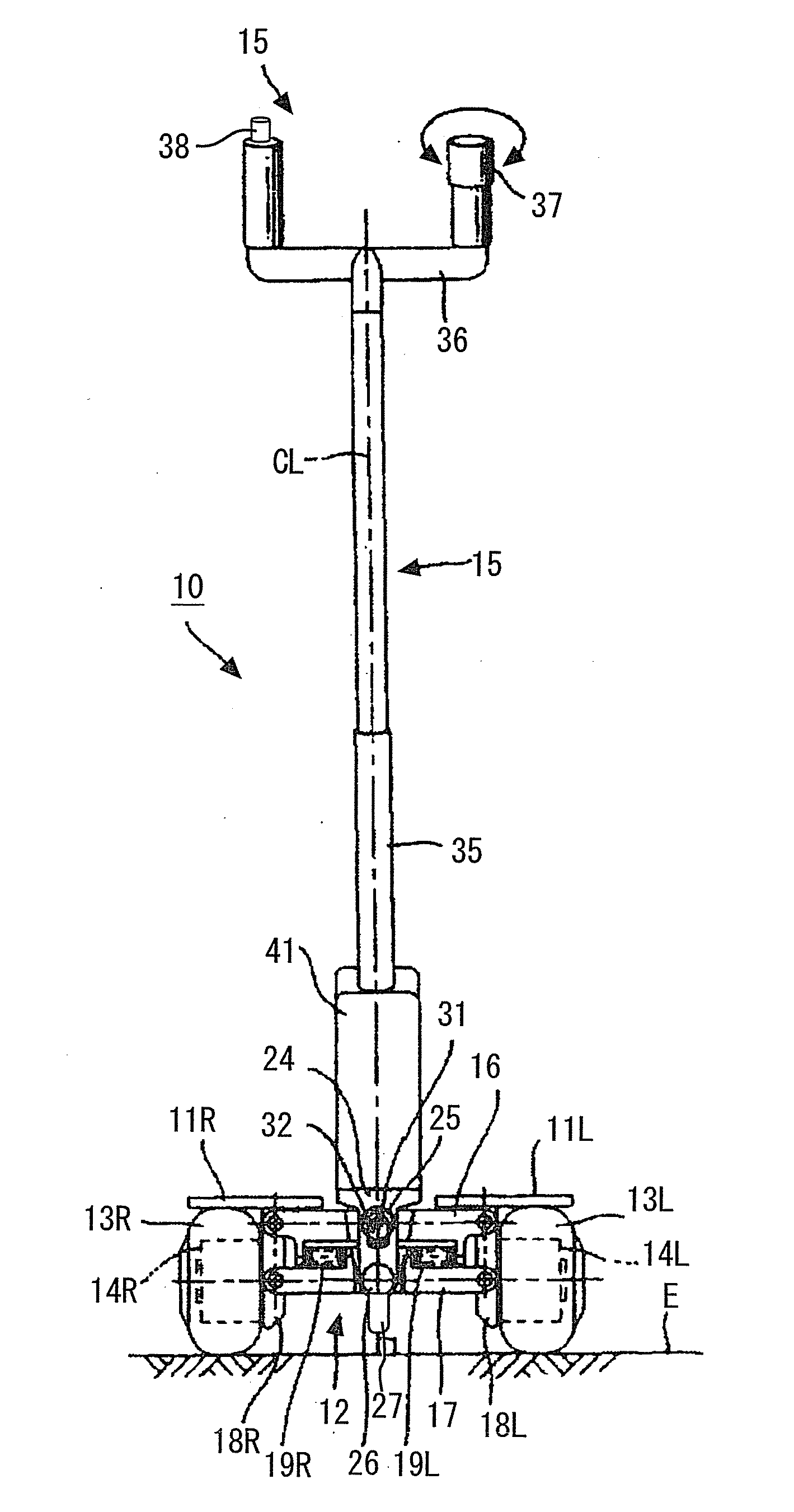
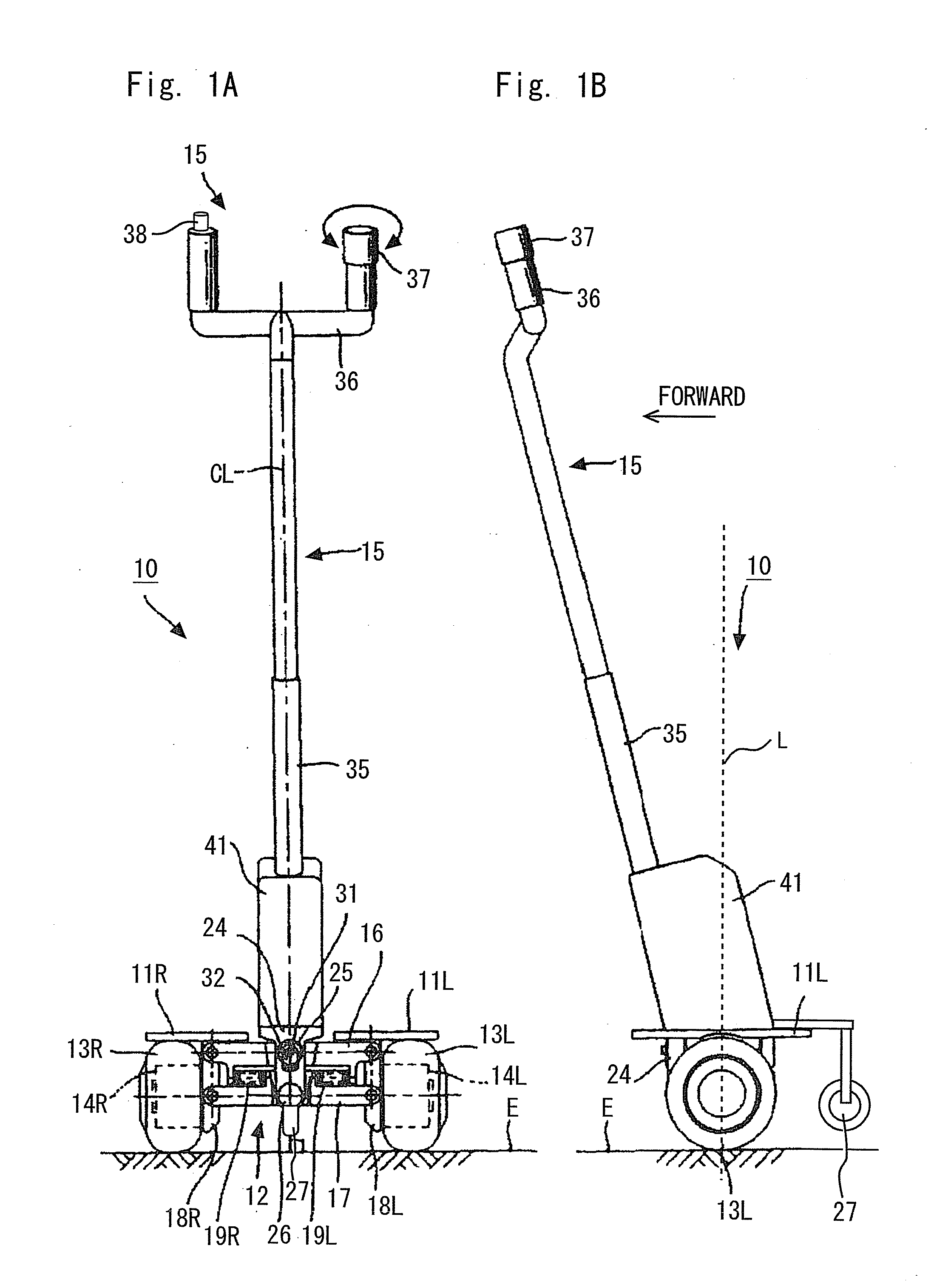
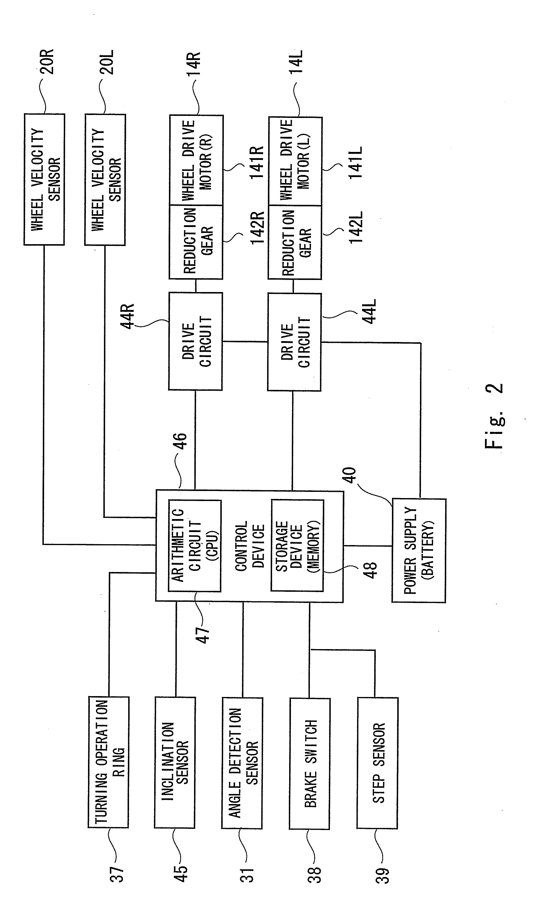
[0028]Exemplary embodiments of the present invention are explained hereinafter with reference to the drawings. FIG. 1A is a front view showing a structure of a traveling device in accordance with a first exemplary embodiment of the present invention, and FIG. 1B is a side view showing a structure of a traveling device in accordance with a first exemplary embodiment of the present invention. Further, FIG. 2 is a block diagram showing an example of a system configuration of a traveling device in accordance with a first exemplary embodiment of the present invention.

[0029]A traveling device 10 in accordance with a first exemplary embodiment of the present invention is applied to, for example, a coaxial two-wheeled vehicle on which a rider rides in a standing posture. However, it is not limited to such an example, and is applicable to any vehicles that perform inversion control including, for example, a wheelchair type vehicle. As shown in FIGS. 1A and 1B, and FIG. 2, the structure of th...

second exemplary embodiment

[0066]A control device 56 of a traveling device 10 in accordance with a second exemplary embodiment of the present invention includes a braking detection unit 46c that detects a braking start trigger in addition to the constituents of the control device 46 of the traveling device 10 in accordance with the first exemplary embodiment (FIG. 6). The braking start trigger indicates a rider's intention for braking.

[0067]The braking detection unit 46c can detects a braking start trigger, for example, by receiving a braking control start signal from a brake switch 38. When the braking detection unit 46c detects the start of braking, it outputs a braking instruction signal to the inversion control unit 46b. When the inversion control unit 46b receives a braking instruction signal from the braking detection unit 46c and receives a detection signal from the ground touching detection unit 46a, it suspends the above-described inversion control. Although the braking detection unit 46c detects the...

third exemplary embodiment

[0074]In a traveling device 10, 20 in accordance with a third exemplary embodiment of the present invention, the inversion control unit 46b of the control device 46, 56 may suspend the inversion control by decreasing the gain value G of the inversion control according to the inclination angle θ of the vehicle main body 12 detected by the inclination sensor 45. The inversion control unit 46b may decrease the gain value G of the inversion control, for example, as the inclination angle θ from the inclination sensor 45 gradually increases and thus the assisting wheel 27 gets closer to the road surface E (FIG. 8).

[0075]For example, as shown in FIG. 8, when an expression 0≦inclination angle θ≦θ1 is satisfied, the gain value G is fixed at a normal gain value G1 (G=G1). Further, when an expression θ1≦inclination angle θ≦θ2 is satisfied, the gain value G gradually decreases with a proportionality constant α(α2≦inclination angle θa is satisfied, the gain value G is fixed at a minute gain valu...


PUM


Abstract

A traveling device 10 includes ground touching detection means to detect a ground touching state in which a ground touching member touches a road surface, and control means to perform inversion control by controlling the driving of a wheel. When a ground touching state of the ground touching member is detected by the ground touching detection means, the control means suspends the inversion control. Further, when the start of braking is detected by the braking detection means and a ground touching state of the ground touching member is detected by the ground touching means, the control means may suspend the inversion control.

Description

INCORPORATION BY REFERENCE[0001]This application is based upon and claims the benefit of priority from Japanese patent Application Publication No. 2009-100497, filed on Apr. 17, 2009, the disclosure of which is incorporated herein in its entirety by reference.BACKGROUND OF THE INVENTION[0002]1. Field of the Invention[0003]The present invention relates to a traveling device that performs inversion control by controlling the driving of a wheel(s) and its control method, in particular to a traveling device capable of performing more stable traveling and its control method.[0004]2. Description of Related Art[0005]Conventionally, coaxial two-wheeled vehicles that perform inversion control by controlling the driving of a wheel(s) have been known (for example, see Japanese Unexamined Patent Application Publication No. 2006-315666). Further, such coaxial two-wheeled vehicles have a problem that, for example, when the inversion control is stopped due to a malfunction or the like, getting on / ...

Claims


Application Information

Patent Timeline
Patent Type & Authority Applications(United States)
IPC IPC(8): G05D1/08
CPCG05D1/0891
Inventor FUWA, TOSHIOTAKEUCHI, YUSHIIZUO, TAKASHI
Owner TOYOTA JIDOSHA KK
Why Eureka
Try Eureka