
Dragline Bucket, Rigging and System

a technology of rigging and buckets, applied in the direction of mechanical machines/dredgers, soil shifting machines/dredgers, construction, etc., can solve the problems of many bucket designs still following old or imperfect rules, affecting the efficiency of dragline operations, and reducing the amount of rigging. the effect of reducing the applied force and stress on the bucket and equipment, speeding up the fill rate, and increasing the payload

Active Publication Date: 2010-10-28
ESCO GRP LLC
View PDF21 Cites 6 Cited by
  • Summary
  • Abstract
  • Description
  • Claims
  • Application Information

AI Technical Summary

Benefits of technology

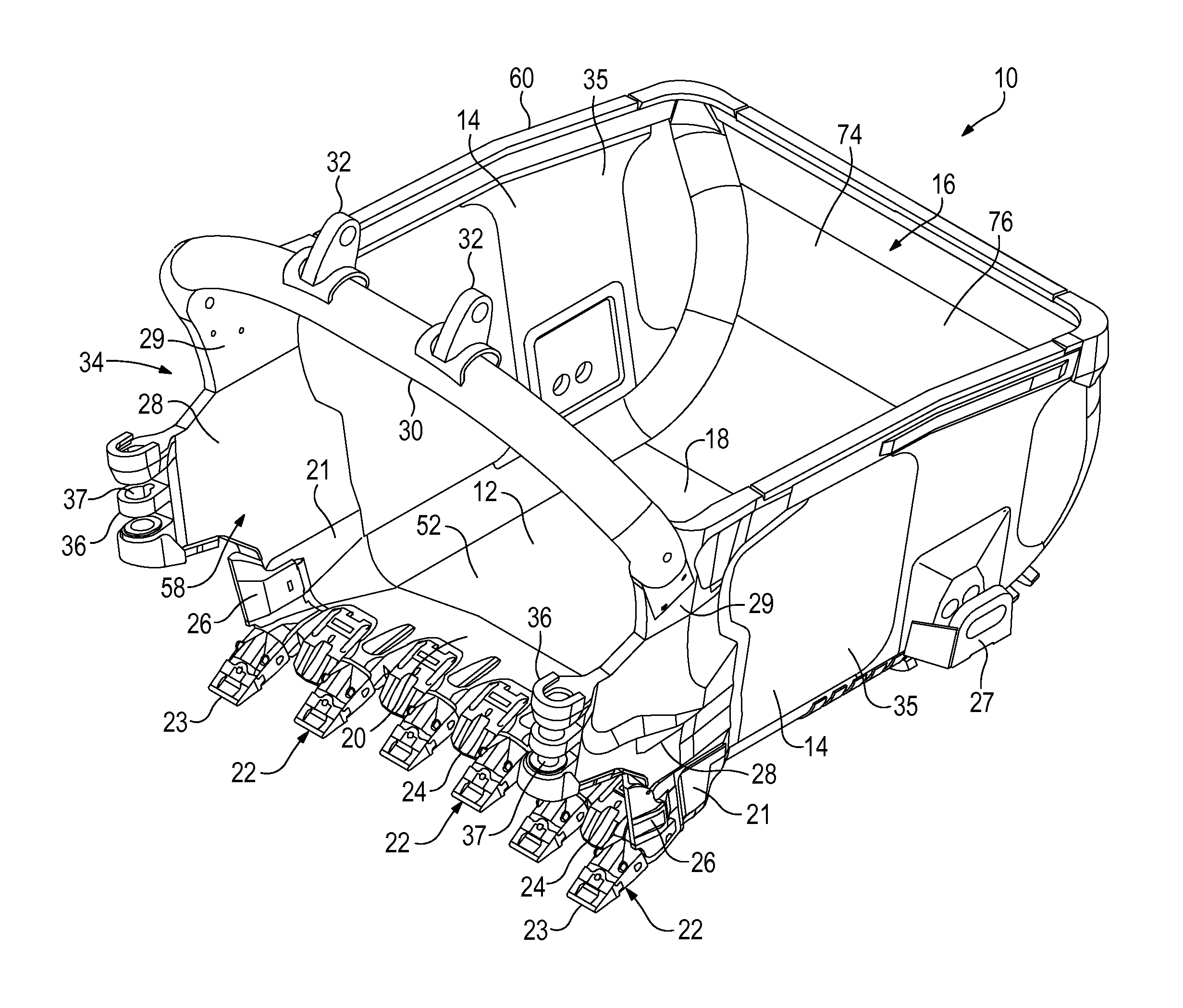
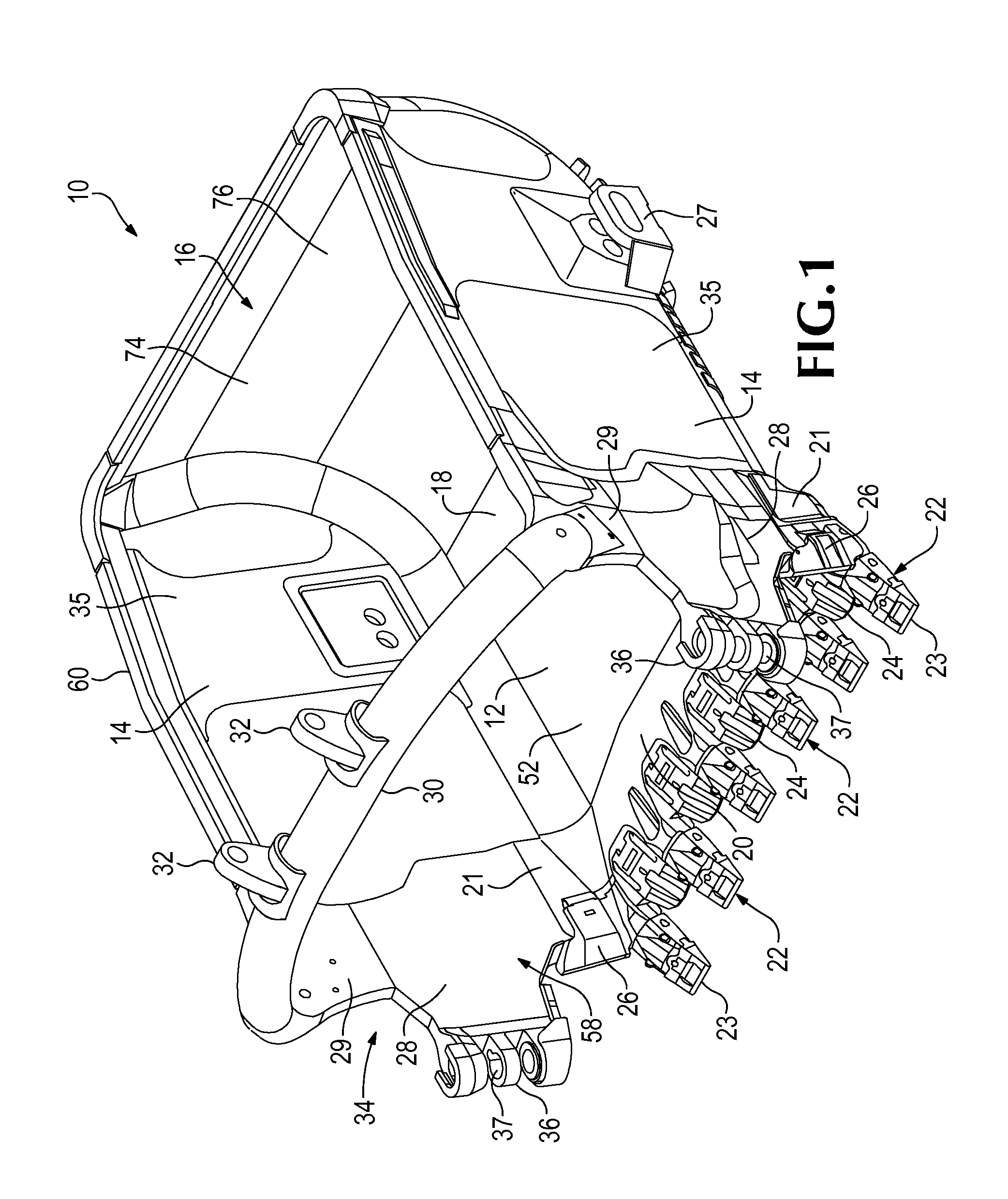
[0009]In accordance with one aspect of the invention, the dragline bucket is formed with a new construction that permits earthen material to be collected with minimum disturbance. This results in a reduction of the applied forces and stresses on the bucket and equipment, increased payload, speedier fill rates, and, in some operations, less need for additional equipment.
[0010]In another aspect of the invention, the sidewalls in at least a forward area of a dragline bucket are provided with a large downward taper of preferably about 7-20 degrees to vertical to improve collection of the earthen material.
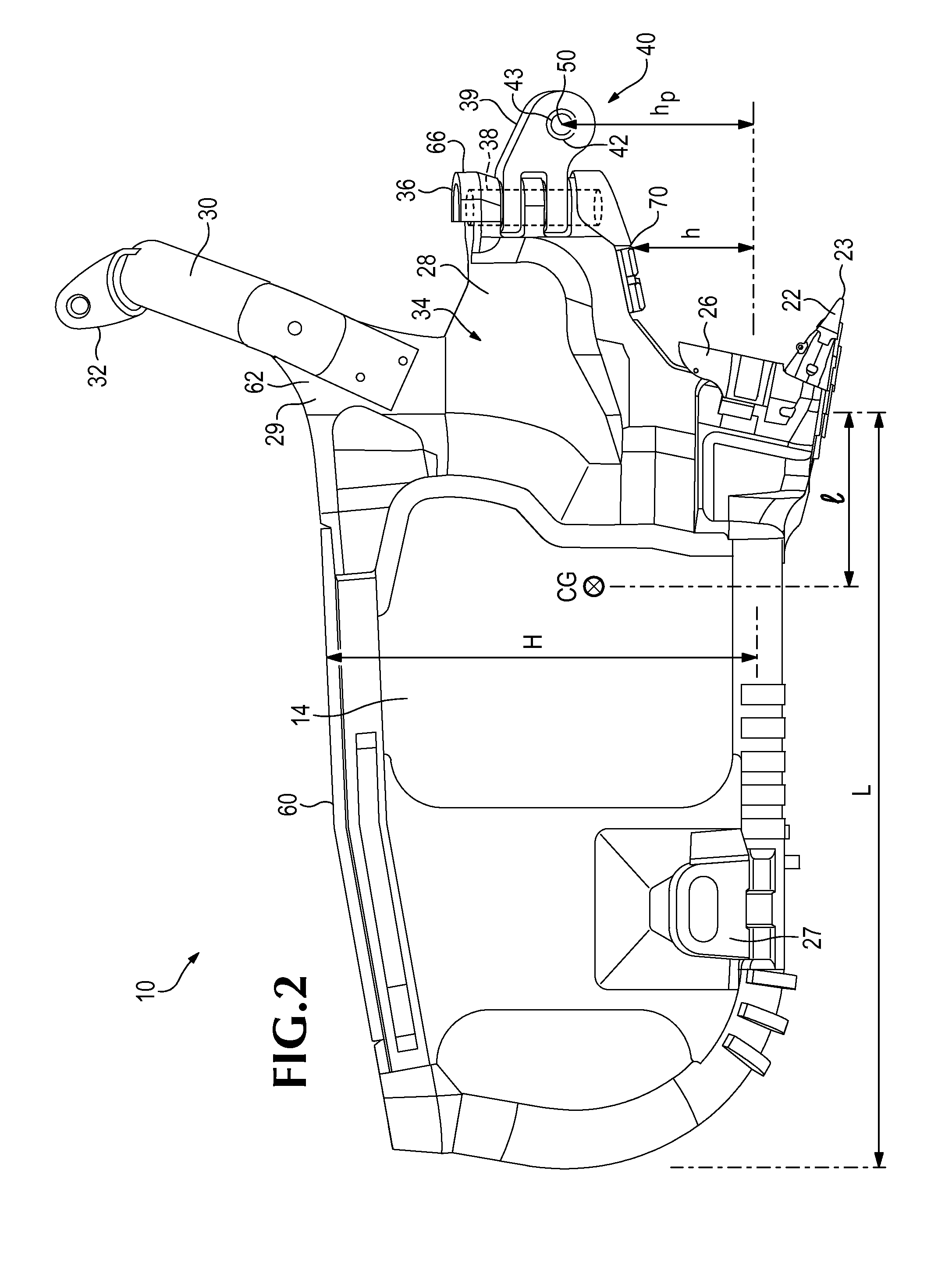
[0011]In another aspect of the invention, a dragline bucket of improved construction and performance is defined by an optimizing balance of the height to length ratio, the sidewall taper, and the hitch pin height to height ratio. In one preferred construction, the height to length of the bucket is about 0.4-0.62, the top to bottom taper of the sidewalls is about 7-20 degrees to vertical, and the hitch pin height to the height of the bucket of at least about 0.3.
[0012]In another aspect of the invention, a large dragline bucket of improved construction and performance can also be achieved by optimizing the hitch pin height to length of the bucket ratio and the hitch pin height to height of the bucket ratio. In one preferred embodiment, a bucket having a capacity of at least 30 cubic yards operating in a mine where the pulling angle of the drag line is less than or equal to about 45 degrees below tub is defined by a hitch pin height to length of the bucket ratio of at least about 0.2, and a hitch pin height to height of the bucket ratio of at least about 0.3.
[0013]In a preferred construction of the invention, the dragline bucket includes an elevated hitch position of at least about one fourth of the average height of the bucket. The use of a high hitch facilitates deeper penetration and digging of the dragline bucket.
[0014]In another aspect of the invention, the sidewalls of a dragline bucket are formed with an upward taper in a rear area of the bucket to eliminate the need for a spreader bar with its associated links and pins, while still connecting the hoist chains to an exterior of the bucket. This arrangement causes minimal disruption to filling and dumping of the bucket, and avoids increased wear of the hoist chains or the bucket. Elimination of the spreader bar also leads to less use of hoist chain. Accordingly, the bucket system enjoys a reduced overall weight of the bucket and rigging, and includes fewer parts to inspect and maintain during use.

Problems solved by technology

Even if a small bucket possess an inefficient design, the difference in fill times is not great because the bucket capacities are small.
However, with the increasing size of machines, mines and desire for greater production, dragline operations have grown considerably in size over time.
Yet, many bucket designs still follow old or imperfect rules that fail to optimize the bucket digging performance.
As a result, many problems still exist in today's dragline buckets.
Even if the bucket is kept in a digging position, it still tends to remain tilted too far forward such that the material is subject to substantial disruption during loading.
Moreover, primarily due to roll piles, great force is required to pull such a tilted bucket through the ground.
On the other hand, buckets with the center of gravity shifted further toward the rear wall tend to penetrate more gradually and with more difficulty, which leads to longer fill times and diminished productivity.
This problem not only requires unnecessary weight being hauled around, but also diminishes the production of each digging stroke, i.e., less new material can be gathered because old material remains in the bucket.
This piling of the material causes it to build up in a heap toward the front of the bucket.
Such heaps also commonly cause roll piles to be formed in front of the buckets (i.e., dirt that heaps up and rolls forward in front of the dragline buckets).
The rigging to accommodate and control such large buckets is also of substantial mass and weight.
The greater the weight of the rigging and the dragline bucket, the lesser the capacity remaining available for loading earthen material within the dragline bucket.
While some efforts have been made to reduce rigging weight, it has largely resulted in only small incremental reductions or led to other undesirable problems.
Further, the bucket and rigging components are exposed to a highly abrasive environment where dirt, rocks, and other debris abrade the rigging and the dragline bucket as they contact the ground.
Connections between rigging elements also experience wear in areas where they bear against each other and are subjected to various forces.
In most modern systems, there are many parts that require such inspection, repair or replacement and it takes significant downtime of the operation to complete the needed tasks.
Such downtime decreases the production and efficiency of the dragline operation.

Method used


Image

  • Dragline Bucket, Rigging and System
  • Dragline Bucket, Rigging and System
  • Dragline Bucket, Rigging and System

Examples


Embodiment Construction

[0042]The present invention pertains to a new and improved dragline bucket and system which provides enhanced performance. The new design enables earthen material to be collected with less disruption and greater efficiency as compared to conventional dragline operations. While the present inventive design is particularly well suited for large dragline mining operations where the bucket has a capacity of 30 cubic yards or more, its aspects can also provide some benefits to other dragline operations. The inventive aspects of the present invention are described in this application in relation to a few exemplary dragline bucket designs, but are usable in a wide variety of bucket configurations. Further, in this application, relative terms are at times used, such as front, rear, up, down, horizontal, vertical, etc., for ease of the description. Nevertheless, these terms are not considered absolute; the orientation of a dragline bucket can change considerably during operation.

[0043]In one...


PUM


Abstract

A dragline bucket includes a bottom wall, a pair of sidewalls and a rear wall that collectively define a cavity. The sidewalls each have a large downward taper of at least about 7 degrees in at least its forward area. In an alternative embodiment, the sidewalls each have an upward taper in its rearward area which alleviates the need for a spreader bar. The dragline bucket collects earthen material with minimal disruption of the material.

Description

BACKGROUND OF THE INVENTION[0001]Dragline excavating systems have long been used in mining and earth moving operations. Unlike other excavating machines, dragline buckets are controlled and supported solely by cables and chains. To a large extent, the stability and performance of the bucket in operation must come from the construction of the bucket.[0002]In smaller buckets, the forces encountered in a dragline operation are not great and the payloads are small. With these buckets, the forces and payloads are easy to compensate for without inhibiting the operation. Even if a small bucket possess an inefficient design, the difference in fill times is not great because the bucket capacities are small. However, with the increasing size of machines, mines and desire for greater production, dragline operations have grown considerably in size over time. In today's mines, large dragline buckets on the order of 30 cubic yards and larger are common, and buckets up to 175 cubic yards are in us...

Claims


Application Information

Patent Timeline
Patent Type & Authority Applications(United States)
IPC IPC(8): E02F3/60
CPCE02F3/60
Inventor KUBO, KENNETHHYDE, STEVEN D.LIAN, AARON B.
Owner ESCO GRP LLC
Learn More