Utility tools and mounting adaptation for a nut driving tool and methods

a technology of nut driving and utility tools, applied in the direction of screwdrivers, power driven tools, wrenches, etc., can solve the problems of difficult use of the driving and reaction tool pair, inability to adapt to the operation, and inability to accurately control the speed of the driving tool, so as to reduce damage and/or deformation, and facilitate use in limited space

Active Publication Date: 2010-10-28
AMERICAN POWER TOOLS
View PDF10 Cites 14 Cited by
  • Summary
  • Abstract
  • Description
  • Claims
  • Application Information

AI Technical Summary

Benefits of technology

[0004]This invention provides apparatus (various tools and adaptations) and methods for associating various utility tools with a nut driving tool. The apparatus accommodate precision facilities fabrication in the field while reducing damage and / or deformity to critical facility components (such as tubing, compression nuts / ferules and the like). The apparatus and methods are well adapted to use with a highly diverse selection of utility tool types thus providing for multifarious fabricating options using a single tool driver. The apparatus, mounting and utility tools of this invention are conducive to use in limited space and are located at only one side of the driving tool.

Problems solved by technology

This precision can be adversely impacted by tubing damage and / or deformity.
Such operations have not always been well accommodated.
In most cases reaction tool wrenches utilized are larger than the fitting of body feature they are engaging, often leading to difficulty in use of the driving and reaction tool pair, particularly where space is limited (as it often is in such installations).

Method used


Image

  • Utility tools and mounting adaptation for a nut driving tool and methods
  • Utility tools and mounting adaptation for a nut driving tool and methods
  • Utility tools and mounting adaptation for a nut driving tool and methods

Examples


first embodiment

[0083]Turning now to FIGS. 5 through 7, a utility tool and adaptation of this invention are illustrated, the adaptation shown having adaptation features common to all embodiments of utility tools disclosed hereinafter. Adaptation 125 is located entirely at one side of a nut driving tool (tool 81 for example) and includes a driver head cover 127 constituting a receiver for utility tool mounting body 129. Mounting body 129 includes a base portion 131 releasably engagable at receiver 127 and station portion 133 on base portion 129 which is releasably engageable by utility tool head 135. Tool head 135 includes mounting interface 136 (an opening for receiving station tower 137 therein; not shown in FIGS. 5 through 7 but identical to the interface identified by the same numeral in FIG. 9).

[0084]Reaction blade receiving slot 139 is sized for friction retention of blade stand 141 of reaction blade unit 143. Reaction blade unit 143 has opening 145 therein for receipt of center nut 109 and tu...

third embodiment

[0102]a utility tool of this invention for tube cutting is described with reference to FIGS. 33 through 38. As with all the utility tools of this invention, cutter tool 371 is mounted entirely at one side of nut driving tool 81. A number of the features of this embodiment are substantially similar to those heretofore described, including the features of adaptation 125, except as addressed herein.

[0103]Threaded pins 375 extend through holes 377 through platform 159 of station portion 133 of mounting body 129. Pins 375 then extend through a set of spaced apart holes 379 in floating guide tower 137 of station portion 133, extending from front surface thereof. Compression springs 381 are mounted over pins 375 and are held captive by a set of threaded nuts 383. Notch 209 is captured and released by latch / catch 183 / 205 as heretofore discussed for firmly holding the mounting. Since base portion 131 is captured against sliding and is secure within slideway 154, the entire tube cutting assem...

fourth embodiment

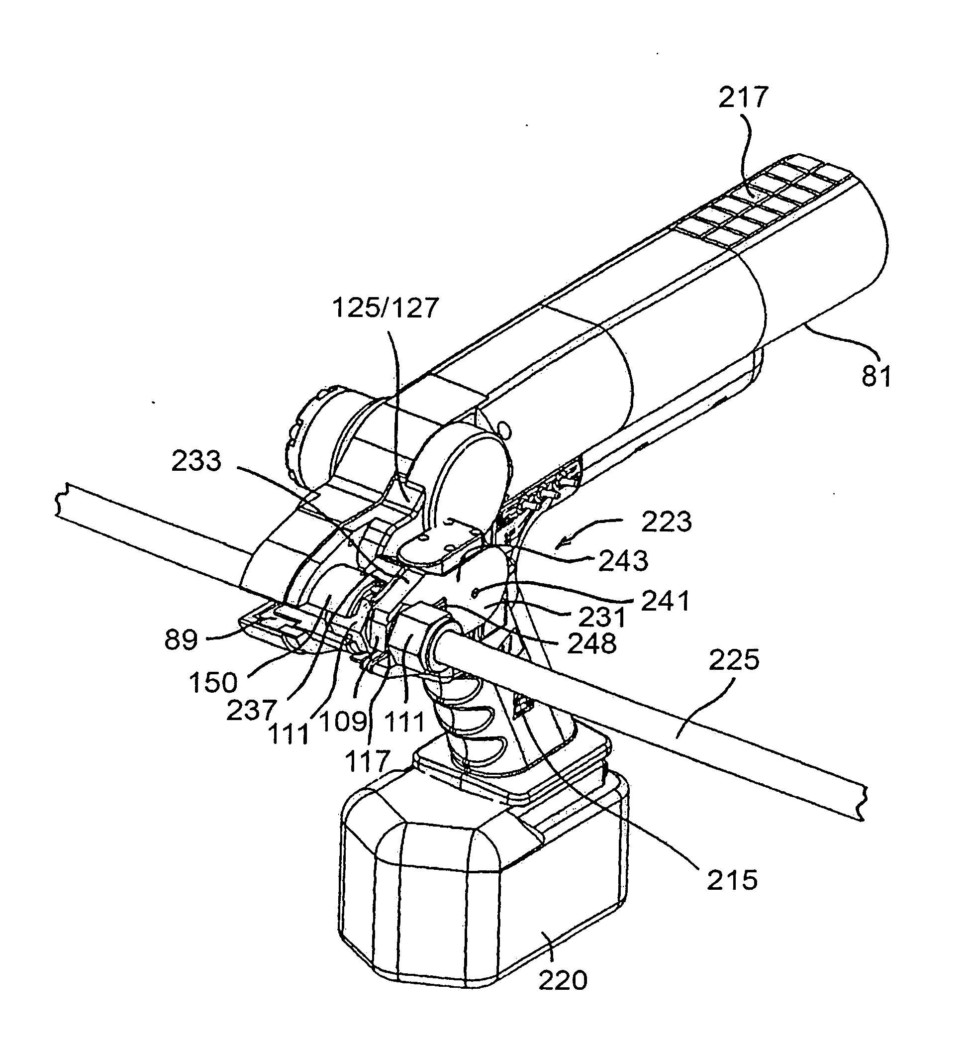
[0107]a utility tool of this invention for tube bending is shown in FIGS. 39 through 44. Bending utility tool 415 of this invention is mounted entirely at one side of nut driving tool 81 for bending tubing 225 as illustrated in FIGS. 39 and 40. As before, a number of the features of this embodiment are substantially similar to those heretofore described, including the features of adaptation 125, except as addressed herein.

[0108]Station portion 133 of mounting body 129 has spring biased rod 417 maintained in opening 419 therethrough and biased outwardly therein by spring 421 and set screw 423 (see FIG. 42). Rod 417 pushes against the end of slideway 154 to bias the tool toward the front adjacent to the output socket 89 of driver 81 (not shown). Bender tool head housing 425 includes retainer section 427 and cover section 429 held together by screws 431. Retainer section 427 has raised pocket 433 centrally located thereat, flanged hub 435 positioning in pocket 433 and secured thereat w...


PUM


Abstract

Adaptations, apparatus and methods are disclosed for associating various utility tools with a nut driving tool. The adaptation of includes a receiver connectable to one side of the nut driving tool adjacent to a socket driver. A utility tool mounting body includes a base portion releasably engageable with the receiver and a station portion on the base portion releasably engageable with the selected utility tool. The utility tool of this invention includes a head having a mounting interface, the station portion releasably engageable with the mounting interface of the utility tool head. In one embodiment, the utility tool is reaction unit for engaging a nut or a fitting body. In other embodiments, utility tools for tube cutting, sawing, and/or bending, and/or grasping of adjacent fitting types or fitting sizes are provided.

Description

FIELD OF THE INVENTION [0001]This invention relates to nut driving tools and methods and, more particularly, to associated appliances used on tube nut drivers.BACKGROUND OF THE INVENTION [0002]Powered drivers, both pneumatic and electrical, for manipulation of various types of tools (such as sockets for threaded connectors) are widely utilized. In many applications, such as manipulation of threaded line fittings (i.e., unions or the like) found in all gas or liquid processing or delivery operations and assemblies, correct tightness of the fitting is critical to assure a sound connection and to avoid leakage (which may occur if line fittings are either over or under tightened thus damaging internal ferrules for example). This precision can be adversely impacted by tubing damage and / or deformity. Moreover, a number of different types of operations and fabrication steps in addition to nut tightening and / or removal are often required to be performed in the field under various circumstan...

Claims


Application Information

Patent Timeline
Patent Type & Authority Applications(United States)
IPC IPC(8): B25B21/00
CPCB25B21/002
Inventor WILSON, JR., DAVIDSIGMON, BRENT A.
Owner AMERICAN POWER TOOLS
Why Eureka
Try Eureka