Separation pump

a technology of separation pump and foaming component, which is applied in the direction of non-positive displacement pump, foam dispersion/prevention, mechanical apparatus, etc., can solve the problems of foaming, and achieve the effects of promoting foam formation, enhancing foaming, and promoting foaming separation

Inactive Publication Date: 2010-10-28
POM TECH
View PDF1 Cites 0 Cited by
  • Summary
  • Abstract
  • Description
  • Claims
  • Application Information

AI Technical Summary

Benefits of technology

[0023]In a preferred embodiment of the invention, the separation pump comprises a set of blades for rotating the fluid mixture at the inlet end of the rotatable drum means. Additional rotating (mixing) of the fluid mixture in addition to rotating the fluid mixture with the rotating drum means promotes the formation of foam and therefore promotes separation of foaming components from the fluid mixture.
[0024]In a preferred embodiment of the invention, the separation pump is provided with a third inlet for feeding an additive i.e. foaming agent into the mixture of gas and suspension or liquid to enhance foaming (forming of foam).

Problems solved by technology

In the past, as for example in a separation pump as disclosed in WO 95 / 17235, foam was considered as a problem in separation pumps and as a problem for the proper function of separation pumps.

Method used


Image

  • Separation pump
  • Separation pump
  • Separation pump

Examples


fifth embodiment

[0050]In the fifth embodiment shown in FIG. 8, rotating vanes 18 for forcing foam through a screen 19 for at least partly breaking down foam extend into an inner space (not marked with a reference number) of the form extraction chamber 21. In FIG. 8, the rotating vanes 18 form also foam moving means 23 for causing foam to flow from the inner space 12 of the rotatable drum means 10 towards the foam discharging means 15. In FIG. 8 the rotating 8 action of the rotating vanes 18 is also preferably, but not necessarily, configured to at least partly break down foam prior feeding and forcing foam through the screen 19.

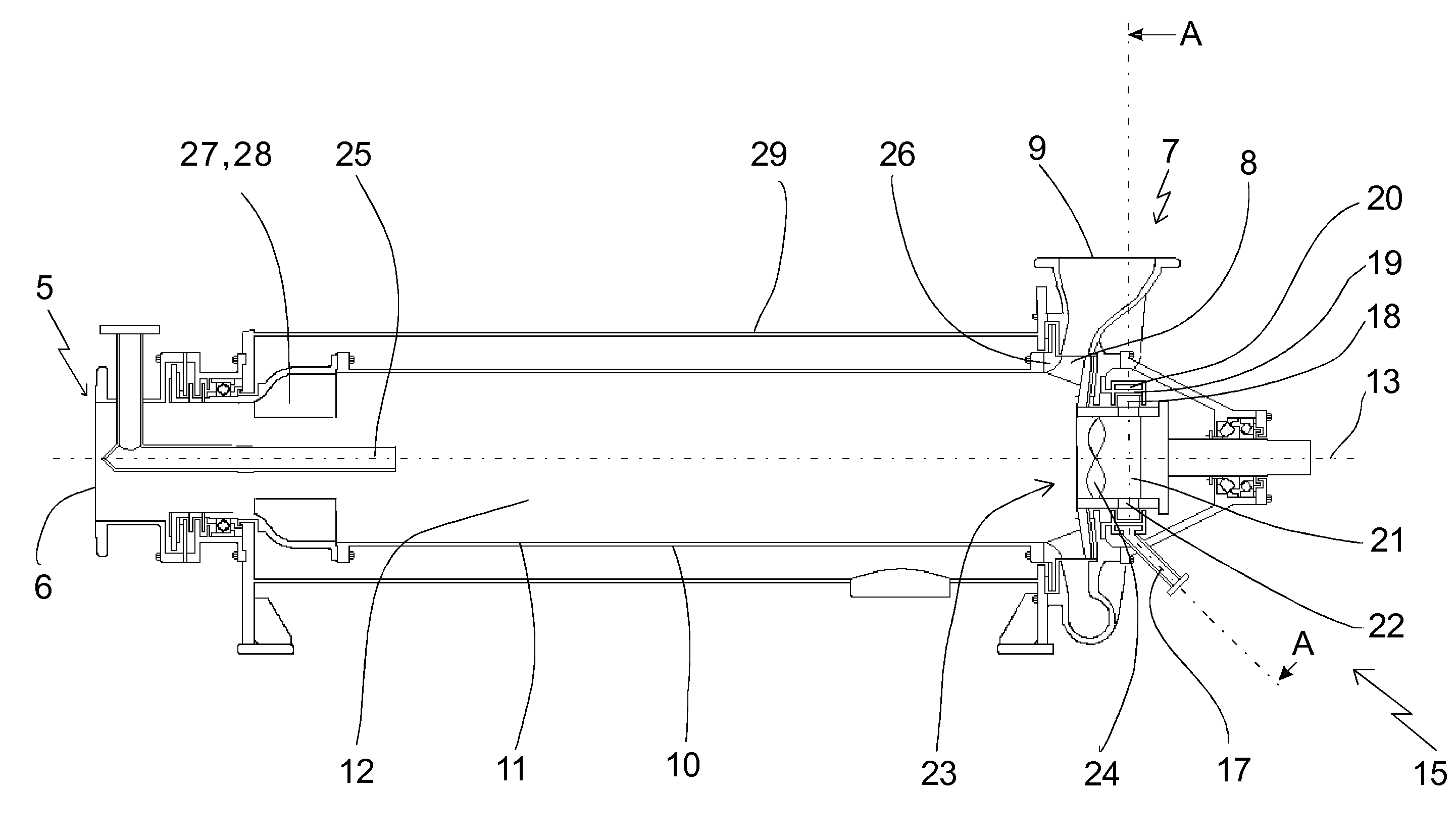
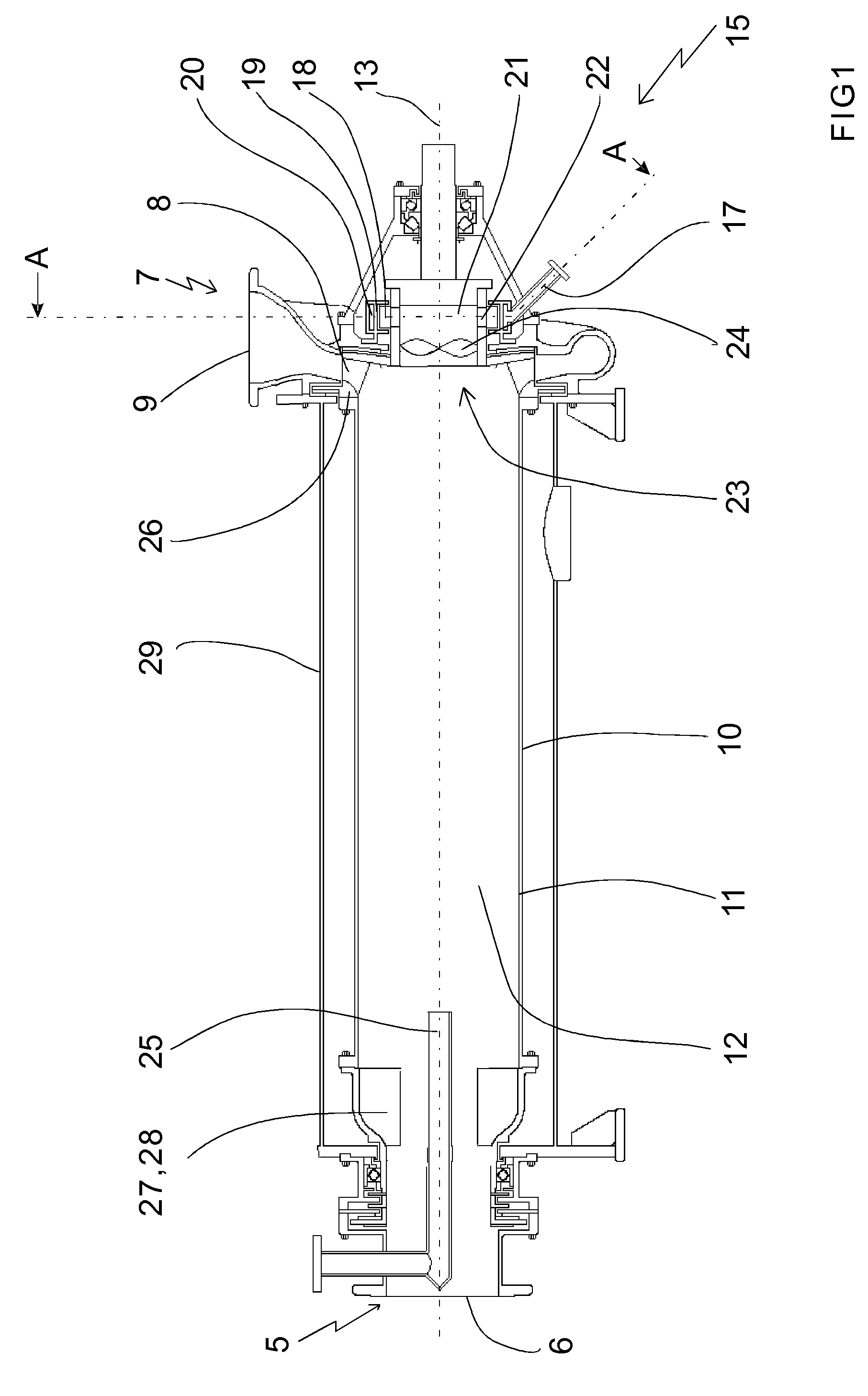
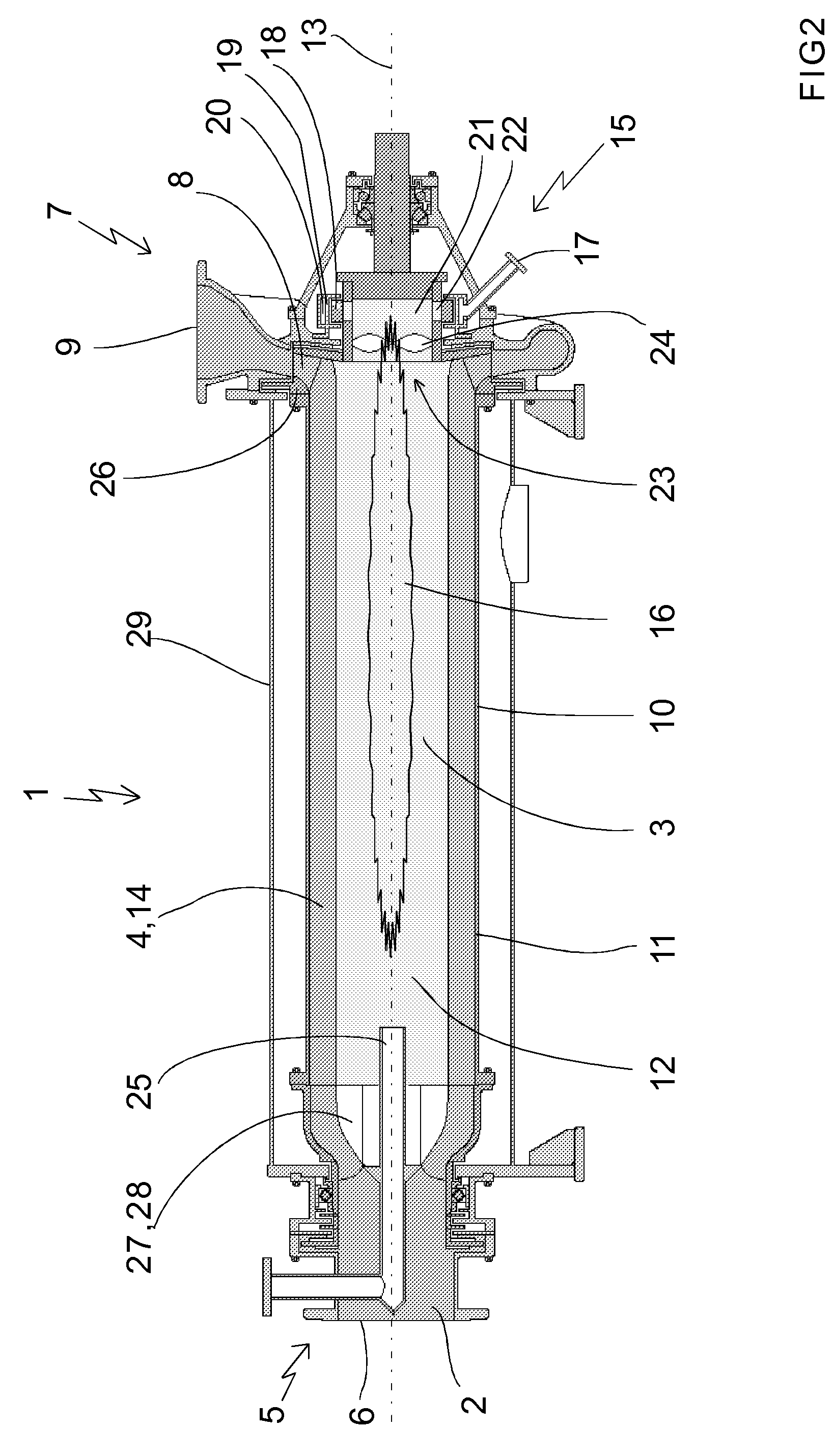
[0051]In FIG. 1, the foam discharging means comprises a foam extraction chamber 21 for receiving foam from the inner space 12 of the rotatable drum means 10. The foam extraction chamber 21 is in FIG. 1 located at the outlet end 7 of the separation pump 1 and located at the axis of rotation of the rotatable drum means 10.

[0052]In FIG. 1, the foam extraction chamber 21 is prov...

fourth embodiment

[0055]FIG. 7 shows a separation pump according to the invention where the form moving means 23 comprises an impeller having rotating radial vanes 37 for causing foam to flow from inner space 12 of the rotatable drum means 10 towards the second outlet 17 of the foam discharging means 15. In FIG. 7, the radial vanes 37 are also configured for at least partly mechanically breaking down foam by hitting the foam with the radial vanes 37 as the radial vanes 37 rotates and foam passes the radial vanes 37 on the way from the inner space 12 of the rotatable drum means 10 to the second outlet 17 prior feeding foam in at least partly broken down state to the second outlet 17.

[0056]The foam moving means 23 are preferably, but not necessarily, arranged at the outlet end 7 of the separation pump 1. In the separation pump shown in FIG. 7, the foam moving means 23 are arranged between the rotatable drum means 10 and the second outlet 17 of the foam discharging means 15. Because the foam moving mean...

second embodiment

[0067]FIG. 4 shows a separation pump according to the invention. The foam discharging means 15 of this separation pump does not comprise any foam breaking means.


PUM

PropertyMeasurementUnit
axis of rotationaaaaaaaaaa
breakingaaaaaaaaaa
pressureaaaaaaaaaa

Abstract

The invention relates to a separation pump (1) for pumping a fluid mixture (2) of gas (3) and liquid or suspension (4) and for separating gas (3) and liquid or suspension (4) from each other. The separation pump (1) comprising a rotatable drum means (10) for rotating fluid mixture (2). The rotatable drum means (10) having an inner wall (11) and an inner space (12). The rotatable drum means (10) being rotatable for causing liquid or suspension (4) of fluid mixture (2) to form a layer of liquid or suspension (4) on the inner wall (11) and for causing gas (3) of the fluid mixture (2) to migrate towards the axis of rotation (13). The separation pump comprises foam discharging means (15) for discharging foam (16) from the inner space (12) of the rotatable drum means (10). The foam discharging means (15) comprises a second outlet (17).

Description

BACKGROUND OF INVENTION[0001]1. Field of the Invention[0002]The present invention relates to a separation pump as claimed in the preamble of independent claim 1.[0003]The present invention relates also to the use of a separation pump.[0004]Gas removal in various process steps such as in various steps of pulping is often inhibited due to foam, which is created in the various process steps, because gas is trapped in the foam or because the foam is so viscous that it prevents free gas flow.[0005]On the other hand, foam can be used for separating components from a mixture, in other words, for separating the components of the foam from the liquid or (liquid) suspension. In addition, foam is an excellent carrier for gas, in other words, for separation of gas from a mixture containing gas and liquid or liquid suspension, since gas is a component of foam. For example in pulp mill processes, foam is a result of air mixing with the soap / tall oil coming from the raw materials. In pulp mill pro...

Claims


Application Information

Patent Timeline
Patent Type & Authority Applications(United States)
IPC IPC(8): B01D19/00D21D5/26F04D7/04
CPCB01D19/0057F04D31/00D21D5/26B01D19/02
Inventor CICHORACKI, TOM
Owner POM TECH
Why Eureka
Try Eureka