
Eureka
For R&D, Eureka makes reading and utilizing patents & technical documents easy.
Eureka AIR
Designed for self-driven R&D workflows. Generate viable solutions, solve complex R&D challenges, empower your innovation with AI.

Eureka Materials
Designed for material experts only. Revolutionize your material R&D, from search, analyze, to developing new materials.

TechResearch
Generate reliable direction feasibility study reports for your R&D in just a few steps.

TechSeek
Discover and master advanced knowledge NOW. Basics, ideas, possibilities, all at once.

TechMind
As an expert in R&D Theories, TechMind can generates customized viable solutions instantly.

TechRisk
Analyze your overall solution with one click, know your potential R&D risks in advance.

TechMonitor
Get weekly tech updates, stay abreast of the latest tech innovations and key insights.
Method for closing a waste bin filling hole and a waste bin
- Summary
- Abstract
- Description
- Claims
- Application Information
AI Technical Summary
Benefits of technology
Problems solved by technology
Method used
Image

Examples
first embodiment
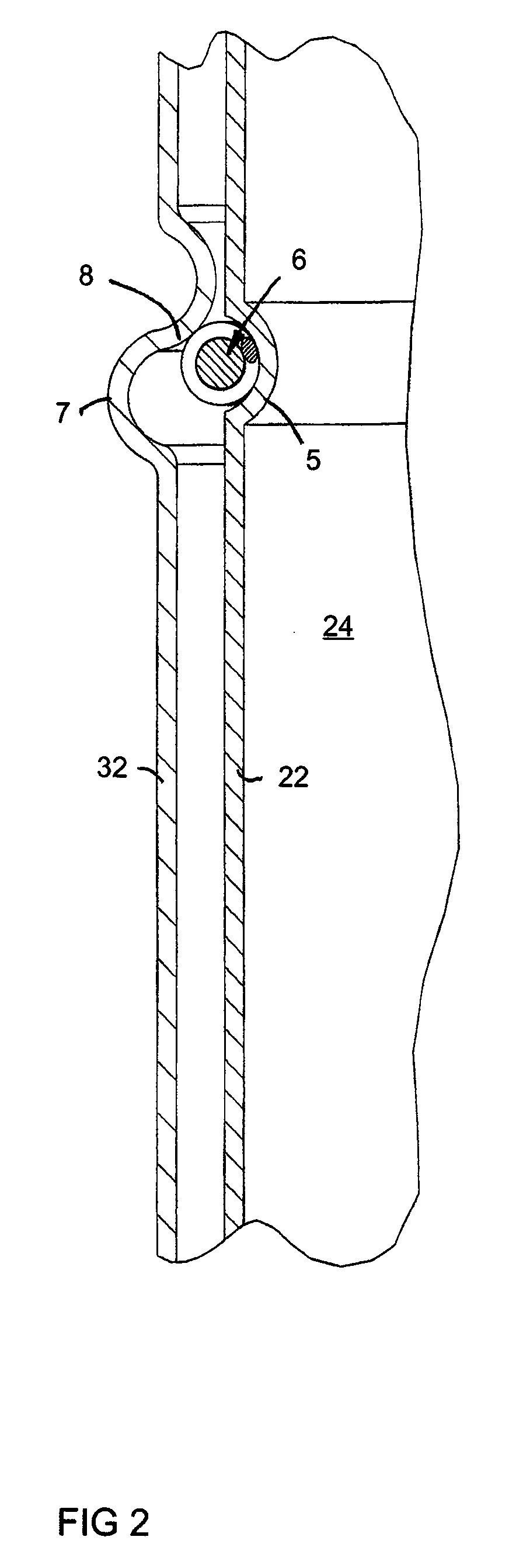
[0037]The retainer part 6 can be totally of shape memory alloy or part of the retainer part is of shape memory alloy. In the embodiment of FIGS. 5-8, the retainer part 6 comprises a core part 61 and a twisted wire part 62 around it. the core part 61 is formed of shape memory alloy. Then, at the temperature T1 i.e. the normal temperature, the shape memory alloy wire forming the core part is ductile and the outer twisted wire part 62 pulls a first end 63 and a second end 64 of the core part 61 together.
[0038]When the temperature reaches the second temperature T2, i.e. the training temperature of shape memory alloy, the core part 61 deforms in a trained way. In the embodiment according to the invention, the core part functions like spring steel after the temperature has risen to the training temperature T2 or above it. The diameter d of the retainer part 6 increases from a first diameter d1 to a second diameter d2 and the length of its circle increases. The ends 63, 64 of the core par...
second embodiment
[0039] the twisted wire part 62 is of shape memory alloy, whereby its length changes after the temperature has reached a predetermined value.
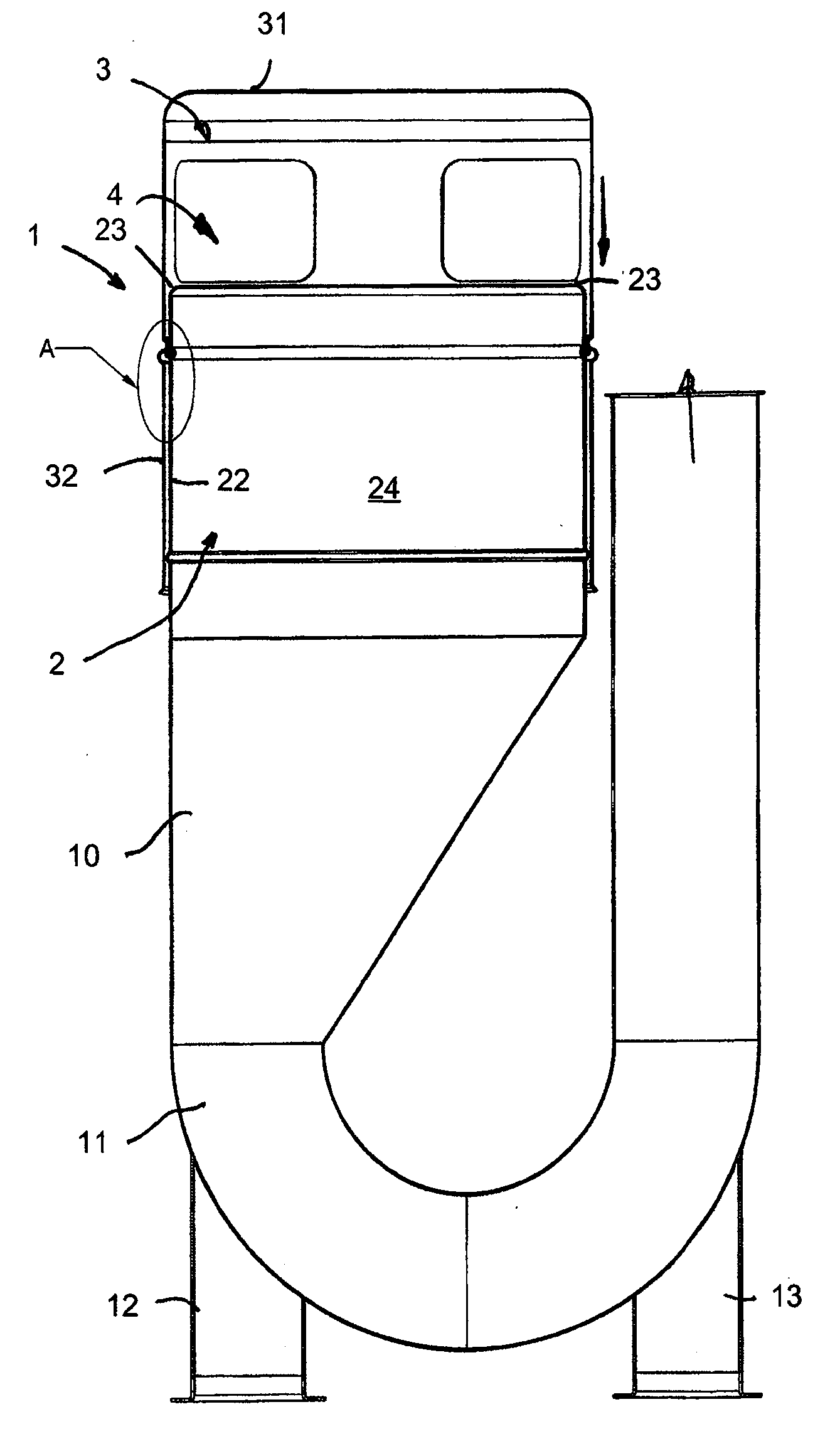
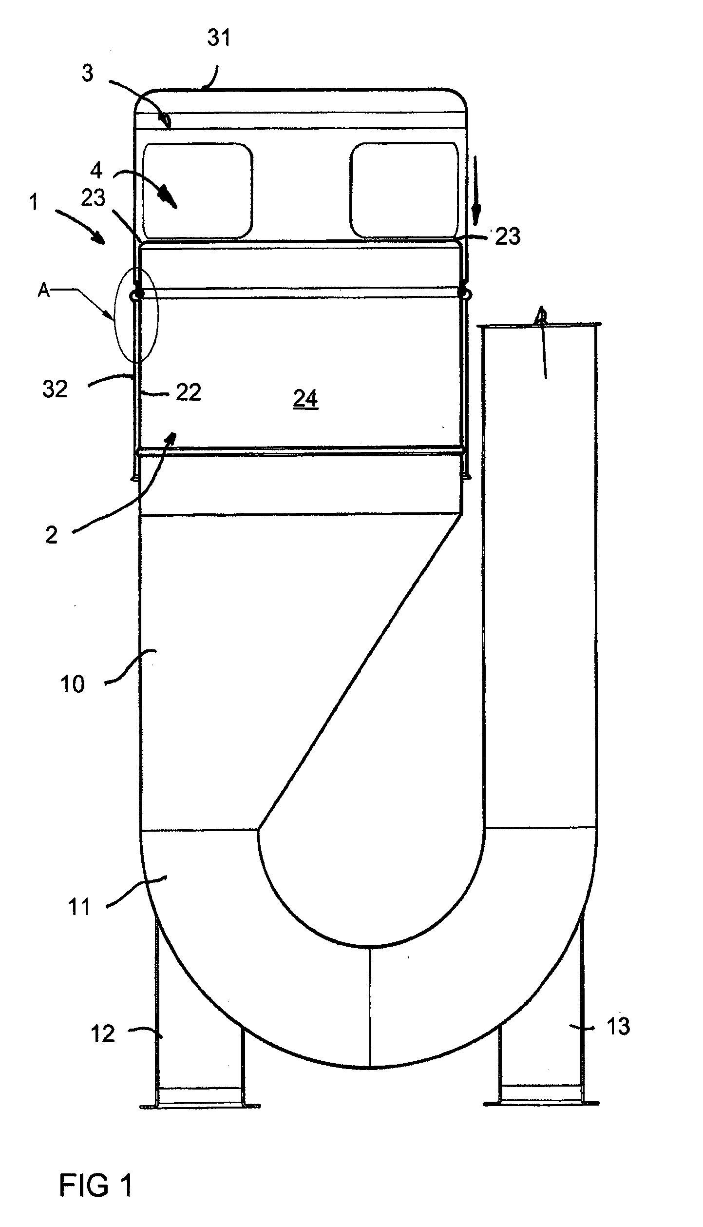
[0040]FIGS. 9-14 show another embodiment of the arrangement according to the invention. In them, the invention has been applied in connection with a conventional waste bin which is not connected, like the first embodiment, to the vacuum conveying system of waste. Furthermore, an embodiment has been illustrated in which the length of the circle of the retainer part 6 shortens (and the diameter d decreases) from the first position to the second position as the temperature rises. FIGS. 9 and 10 show the waste bin 1 in the first position in which the filling holes 4 are open and waste can be set via them to the container part 2. In the embodiment, the container part 2 is a vessel which comprises a bottom 21 and side walls 22 extending upwards from it. The cross-section of the side wall part is mainly peripherical, e.g. circular or elliptical. The c...
PUM
 Abstract
Description
Claims
Application Information
 - R&D Engineer
- R&D Manager
- IP Professional
- Industry Leading Data Capabilities
- Powerful AI technology
- Patent DNA Extraction
Browse by: Latest US Patents, China's latest patents, Technical Efficacy Thesaurus, Application Domain, Technology Topic, Popular Technical Reports.
© 2024 PatSnap. All rights reserved.Legal|Privacy policy|Modern Slavery Act Transparency Statement|Sitemap|About US| Contact US: help@patsnap.com