Butterfly valve assembly including a bearing assembly for serrated spline constraint

a technology of bearing assembly and serrated spline, which is applied in the direction of valve housing, mechanical equipment, transportation and packaging, etc., can solve the problems of radial and angular misalignment at the serrated spline interface, affecting the service life of the valve, and exhibiting some drawbacks, so as to minimize the misalignment of the serrated spline coupling and minimize the misalignment of the serrated splin

Inactive Publication Date: 2010-10-28
HONEYWELL INT INC
View PDF9 Cites 27 Cited by
  • Summary
  • Abstract
  • Description
  • Claims
  • Application Information

AI Technical Summary

Benefits of technology

[0011]In yet another embodiment, by way of example only, the valve includes a flowbody having an inner surface defining a channel; a butterfly plate disposed in the channel and rotationally mounted to the flowbody, the butterfly plate having a valve shaft coupled thereto and positioned at an angle to the inner surface of the flowbody; an actuator having an actuator output shaft coupled to the valve shaft via a serrated spline coupling, the actuator configured to actuate the butterfly plate; an upper bearing assembly disposed within the flowbody and comprising a inboard bearing and an outboard bearing, and a shim stack, the outboard bearing configured to encompass an upper end of the valve shaft and the serrated spline coupling, the inboard bearing comprising an inner race, an outer race and ...

Problems solved by technology

Although the aforementioned valve configuration including a serrated spline coupling operates adequately, it may exhibit some drawbacks.
For example, when the valve is operational, misalignment at the serrated spline interface, and more particularly at an interface between the actuator output shaft and the butterfly valve shaft, may occur.
More specifically, the flow of fluid through the valve flowbody may cause differential pressure across the butterfly plate causing the butterfly valve shaft to deflect (bow) between a ball bearing that supports the butter...

Method used


Image

  • Butterfly valve assembly including a bearing assembly for serrated spline constraint
  • Butterfly valve assembly including a bearing assembly for serrated spline constraint
  • Butterfly valve assembly including a bearing assembly for serrated spline constraint

Examples


Embodiment Construction

[0018]The following detailed description of the inventive subject matter is merely exemplary in nature and is not intended to limit the inventive subject matter or the application and uses of the inventive subject matter. Furthermore, there is no intention to be bound by any theory presented in the preceding background of the inventive subject matter or the following detailed description of the inventive subject matter.

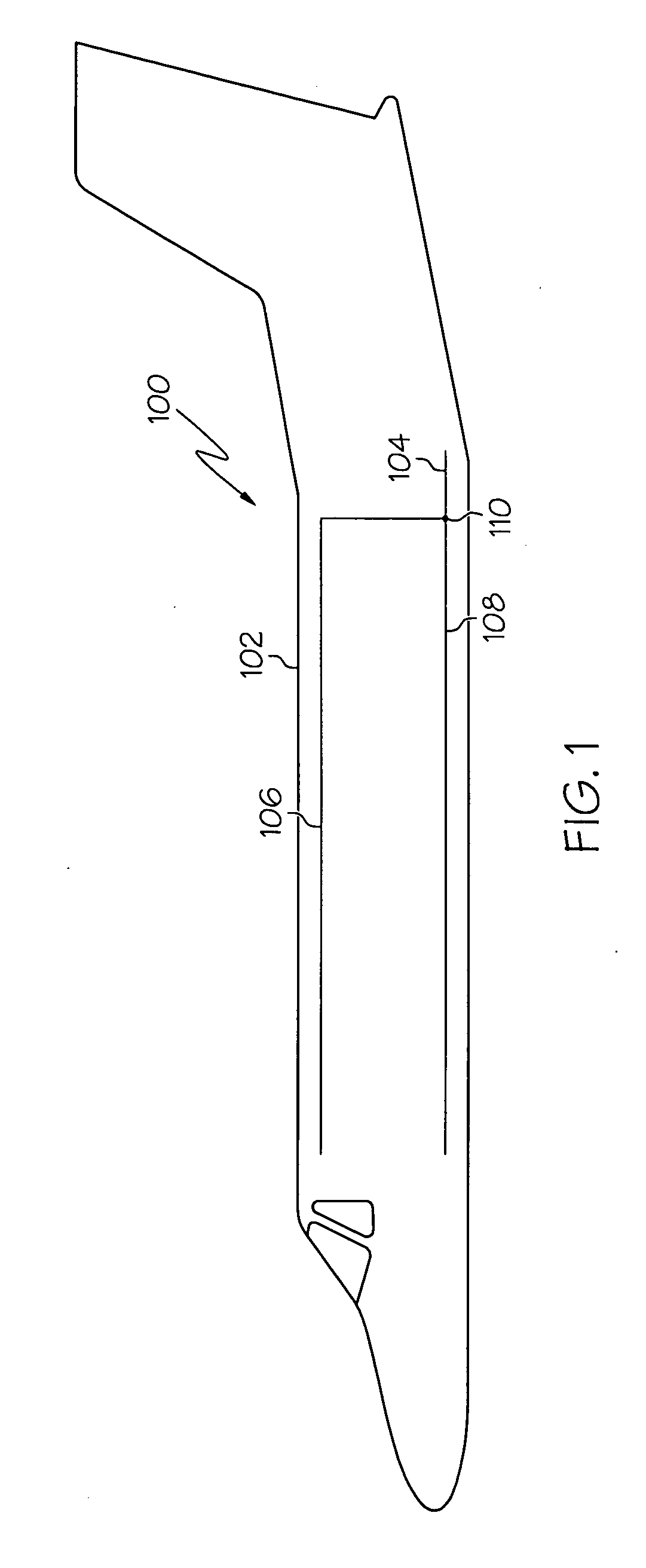
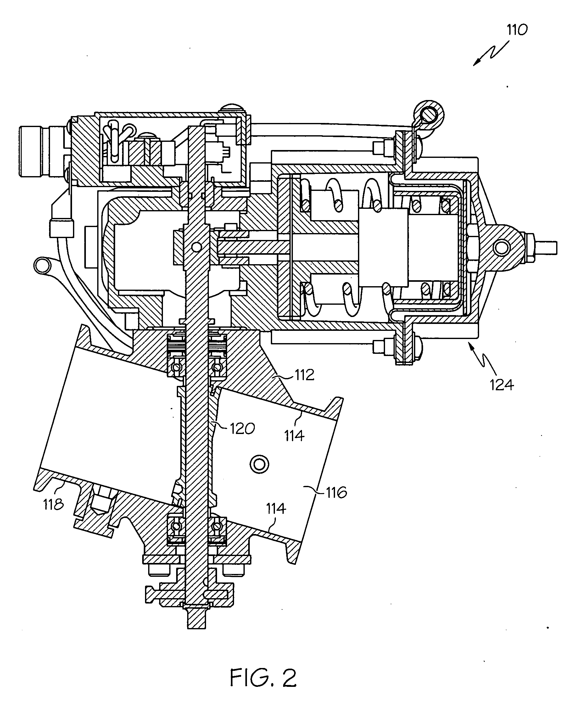
[0019]FIG. 1 is a simplified schematic diagram illustrating an air distribution system 100 disposed within an aircraft 102, according to an embodiment. The air distribution system 100 includes an inlet duct 104, two outlet ducts 106, 108 and a valve assembly 110 positioned between the ducts 104, 106, 108. The inlet duct 104 receives air from an air source, such as, for example, engine bleed air, and the outlet ducts 106, 108 exhaust air into desired sections of the aircraft 102. In one exemplary embodiment, the outlet ducts 106, 108 exhaust air into an aircraft underf...


PUM


Abstract

Butterfly valves assemblies are provided that include a flowbody, a butterfly plate, an actuator and an upper chimney and a lower chimney disposed within the flowbody. The flowbody has an inner surface defining a channel. The butterfly plate is disposed in the channel, is rotationally mounted to the flowbody, and has an outer periphery. The actuator has an actuator output shaft that is coupled to the valve shaft via a serrated spline coupling. The upper chimney and the lower chimney are configured to include bearing assemblies that constrain radial loads and thrust loads exerted upon the valve shaft and minimize misalignment of the serrated spline coupling.

Description

TECHNICAL FIELD[0001]The inventive subject matter relates to pneumatic valve assemblies and, more particularly, to butterfly valve assemblies including a serrated spline coupling.BACKGROUND[0002]Valves may be employed in any one of numerous situations. For example, valves may be used in an air distribution system to direct airflow from one portion of an aircraft to another. In this regard, pneumatic valves may be disposed in a duct between an air source and one or more outlets for exhausting the received air to desired areas within the aircraft, such as, for example, to an aircraft cabin or an underfloor section of the aircraft.[0003]One exemplary type of pneumatic valve that has been employed in aircraft is a butterfly valve. A butterfly valve is typically made up of a valve flowbody and a butterfly plate. The valve flowbody may be made of a rigid material, such as metal, and includes an inner surface defining a channel. The valve flowbody is configured to be disposed between two d...

Claims


Application Information

Patent Timeline
IPC IPC(8): F16K1/22
CPCB64D13/02F16K27/0218F16K1/224F16C19/06F16C19/54F16C25/083F16C41/02
Inventor MENDOZA, ANTHONYKOLIC, MIKESMITH, DOUGHO, BENGAINES, LOUIE TIMOTHY
Owner HONEYWELL INT INC
Why Eureka
Try Eureka