Tool coolant application and direction assembly

Inactive Publication Date: 2010-10-28
BECKINGTON KEVIN
View PDF45 Cites 25 Cited by
  • Summary
  • Abstract
  • Description
  • Claims
  • Application Information

AI Technical Summary

Benefits of technology

[0008]Accordingly, the example tool holder provides easy mounting to existing machinery while directing coolant along the entire

Problems solved by technology

Without coolant flow, friction from the tool and the workpiece generate heat of a degree sufficient to decrease tool life.
Often during the machining, the work piece or chips bump and contact the coolant lines changing the position of the hose such that the coolant is no longer directed as originally positioned onto the tool.
In addition, hoses are often not positionable for providing coolant as desired when machining of relatively deep openings or holes.
Further, in some part configurations an adjusta

Method used


Image

  • Tool coolant application and direction assembly
  • Tool coolant application and direction assembly
  • Tool coolant application and direction assembly

Examples


Example

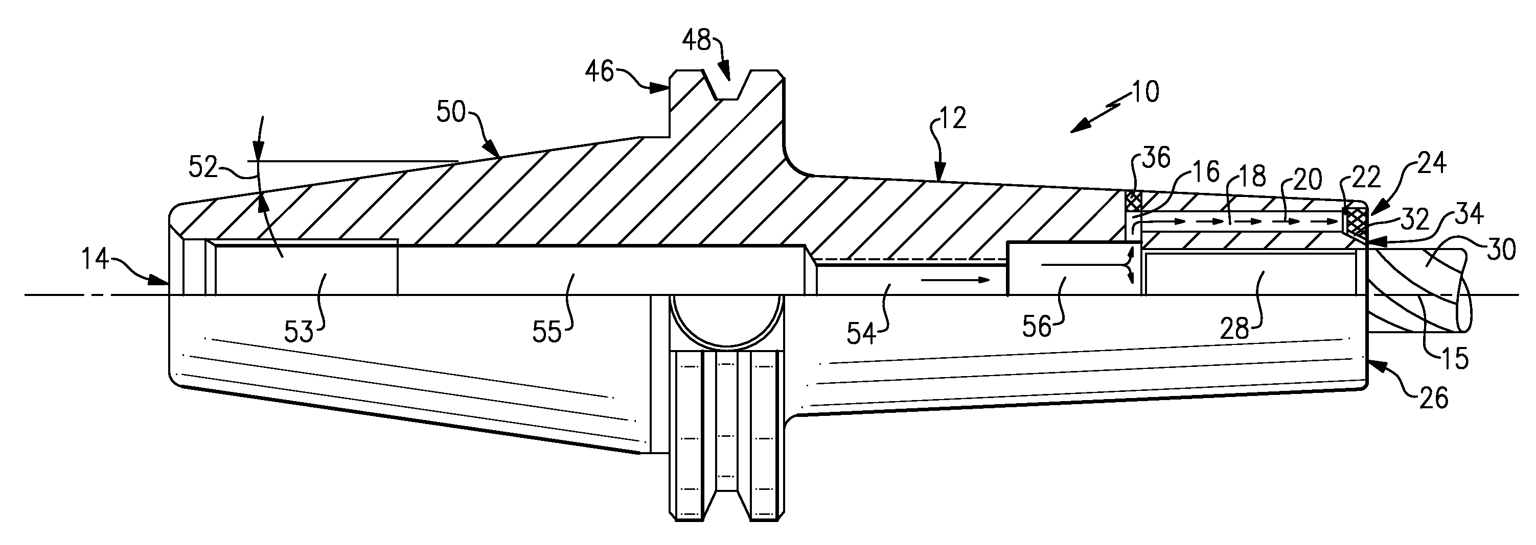
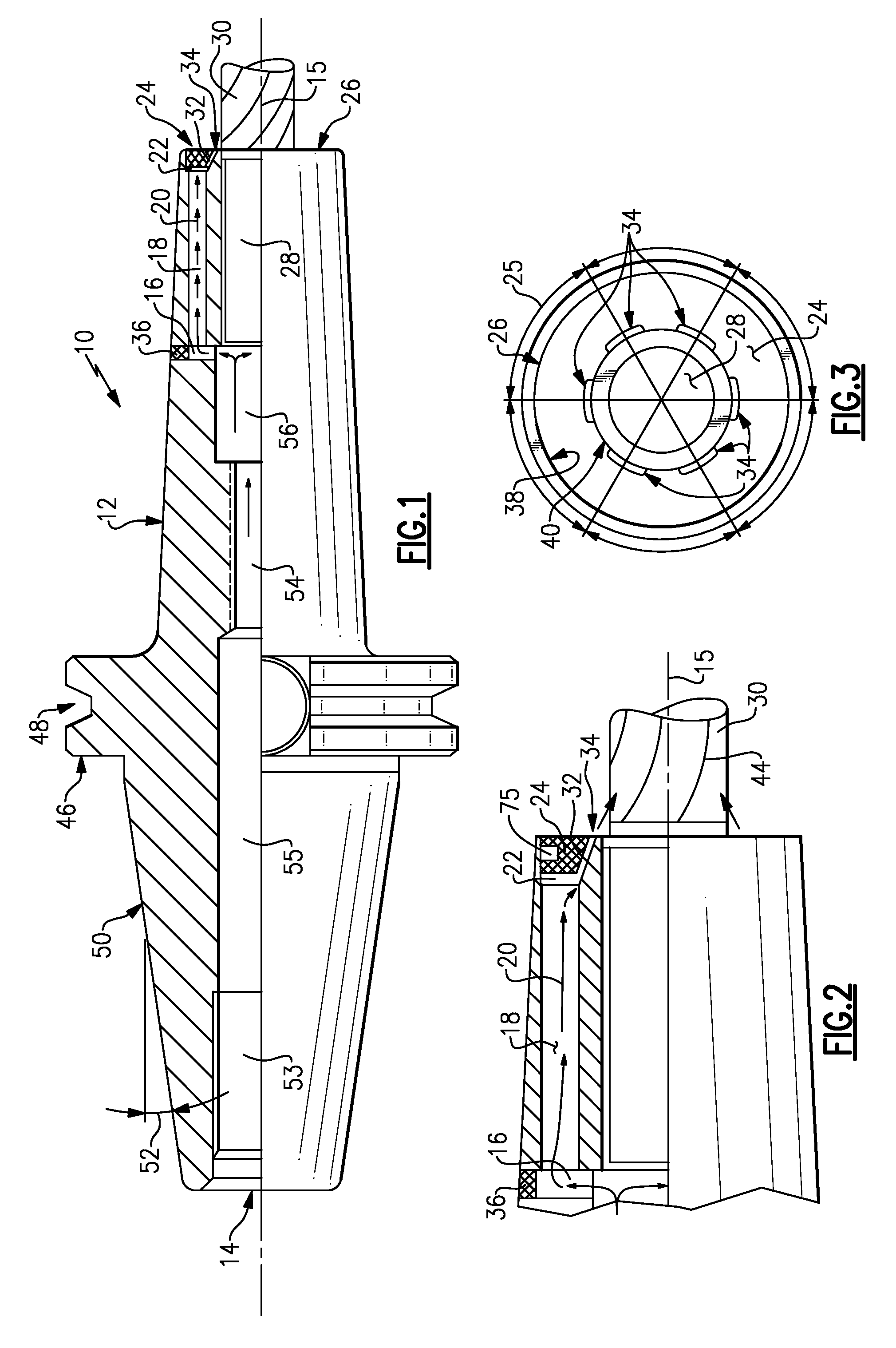
[0018]Referring to the FIG. 1, an example tool holder assembly 10 holds a tool 30 for mounting with a machine tool (not shown). The example tool holder 10 is an end mill holder, however other tool holders as are known will benefit from the disclosures herein. The tool holder 10 includes a body 12 having an inlet 14 through which coolant (indicated by arrows 20) flows to lateral passages 16 that are in turn in fluid communication with coolant passages 18. Although the example tool holder assembly 10 includes an inlet through a rear portion, coolant may also be introduced through other portions of the tool holder 10, such as for example through a flange portion 46. The coolant passages 18 are in fluid communication with and annular fluid channel 22. The annular fluid channel 22 is in turn in fluid communication with passages 32 defined by an insert 24 and a conical wall 40. Coolant directed through the passage 32 exits through ports 34 at a desired angle and velocity to impact the too...


PUM

PropertyMeasurementUnit
Angleaaaaaaaaaa
Angleaaaaaaaaaa
Distanceaaaaaaaaaa

Abstract

A tool holder includes an insert having an annular channel in fluid communication with an inlet. The insert mounts within a body that provides for rigidly mounting the tool to the machine. Coolant flow through the inlet and annular channel exits the insert through passages directing coolant fluid along the axis of the tool. The passages are annularly disposed about a face of the insert for directing coolant fluid along the tool.

Description

REFERENCE TO RELATED APPLICATIONS[0001]This application is a continuation-in-part of U.S. patent application Ser. No. 11 / 636,012 filed Dec. 7, 2006 which is continuation-in-part of co-pending U.S. application Ser. No. 11 / 098,979 filed on Apr. 5, 2005 which is a continuation-in-part of U.S. application Ser. No. 10 / 197,390 filed on Jul. 17, 2002, now U.S. Pat. No. 7,134,812, issued on Nov. 14, 2006.BACKGROUND OF THE INVENTION[0002]This disclosure relates to a tool holder that includes features for directing coolant flow onto a tool workpiece interface. More specifically, this disclosure relates to a tool holder that includes openings that directs coolant flow to maintain a desired fluid flow rate at the tool workpiece interface regardless of tool rotational speed.[0003]Conventional machining process may utilize a stream of coolant directed onto the cutting tool to maintain a constant temperature. Without coolant flow, friction from the tool and the workpiece generate heat of a degree ...

Claims


Application Information

Patent Timeline
IPC IPC(8): B23C5/28B23C5/26B23P15/00
CPCB23B31/1179B23B2231/04B23B2231/24B23C5/10Y10T279/17111B23Q11/1015B23B2250/12Y10T407/14Y10T29/49826B23Q11/10
Inventor BECKINGTON, KEVIN
Owner BECKINGTON KEVIN
Why Eureka
Try Eureka