Charging control device and electricity storage system

a control device and control device technology, applied in the integration of power network operation systems, transportation and packaging, ac network load balancing, etc., can solve the problems of not being able to disclose a constant deterioration reduction method and failure to disclose a deterioration reduction method, so as to achieve effective reduction of battery deterioration

Active Publication Date: 2010-10-28
DENSO CORP
View PDF6 Cites 15 Cited by
  • Summary
  • Abstract
  • Description
  • Claims
  • Application Information

AI Technical Summary

Benefits of technology

[0011]Accordingly, battery deterio

Problems solved by technology

However, JP-B2-3827676 or JP-A-2003-9418 fails to disclose a reducing of battery deterioration in

Method used


Image

  • Charging control device and electricity storage system
  • Charging control device and electricity storage system
  • Charging control device and electricity storage system

Examples


first embodiment

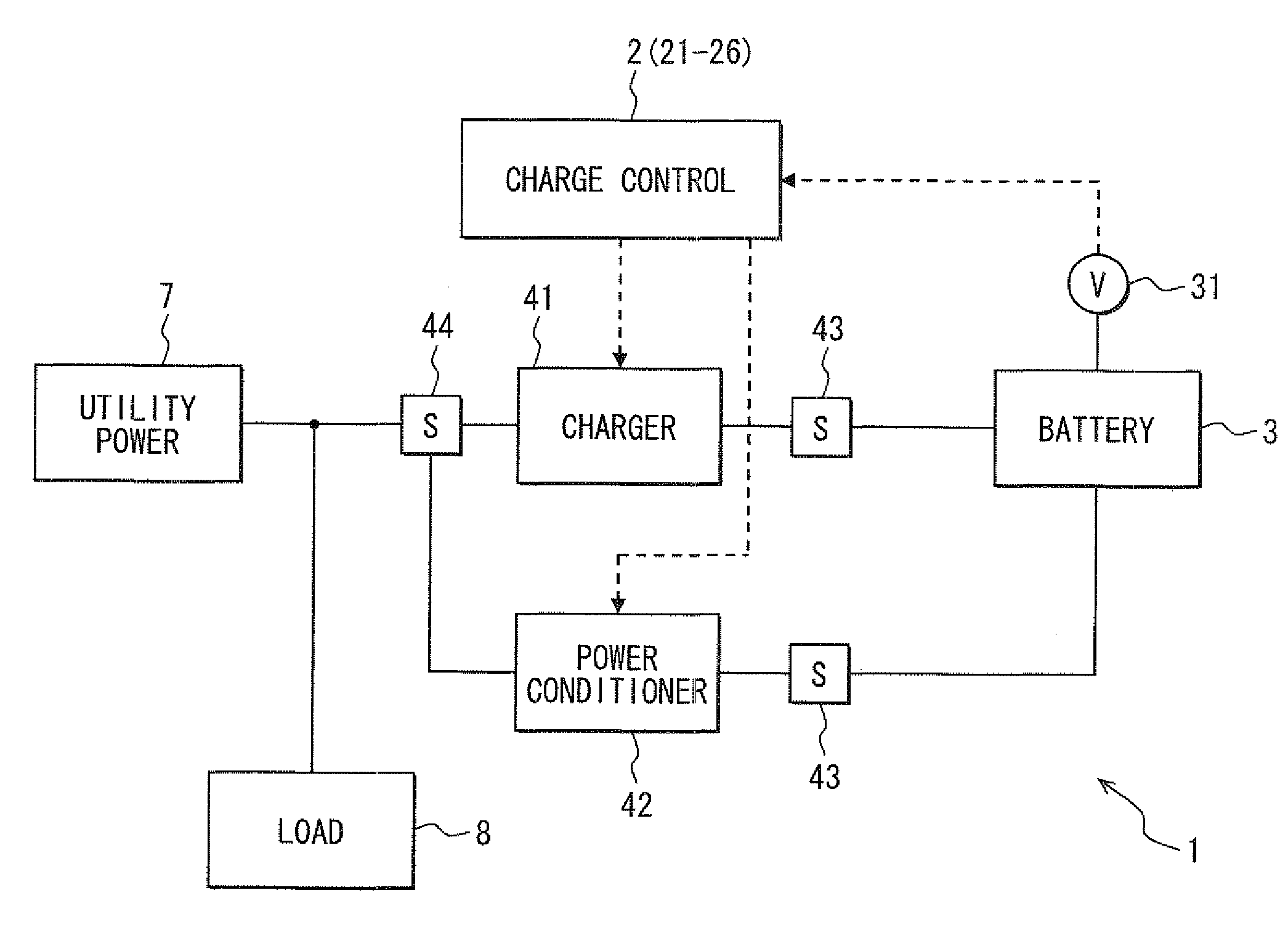
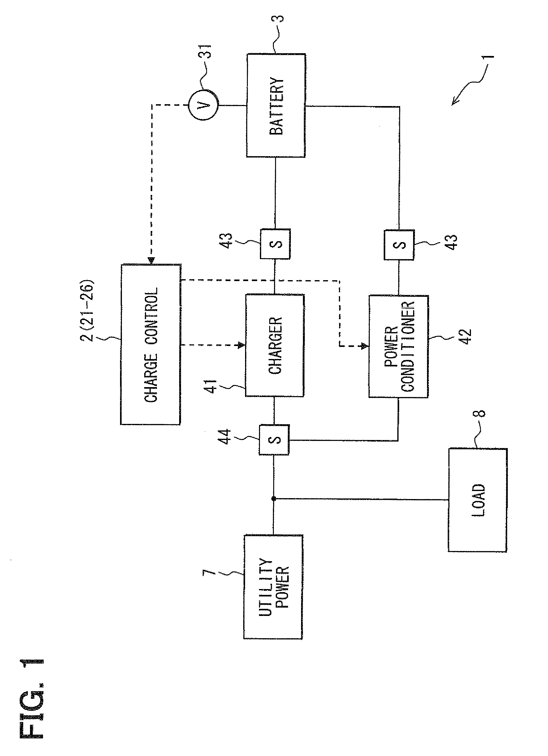
[0024]As shown in FIG. 1, a charging control device 2 is used in an electricity storage system 1. The charging control device 2 may correspond to a charging and discharging control device. The device 2 controls a charger 41 to charge a battery 3 by using a utility power source 7. The battery 3 is charged in nighttime B, and the charged electricity is discharged from the battery 3 to a load 8 in daytime A.

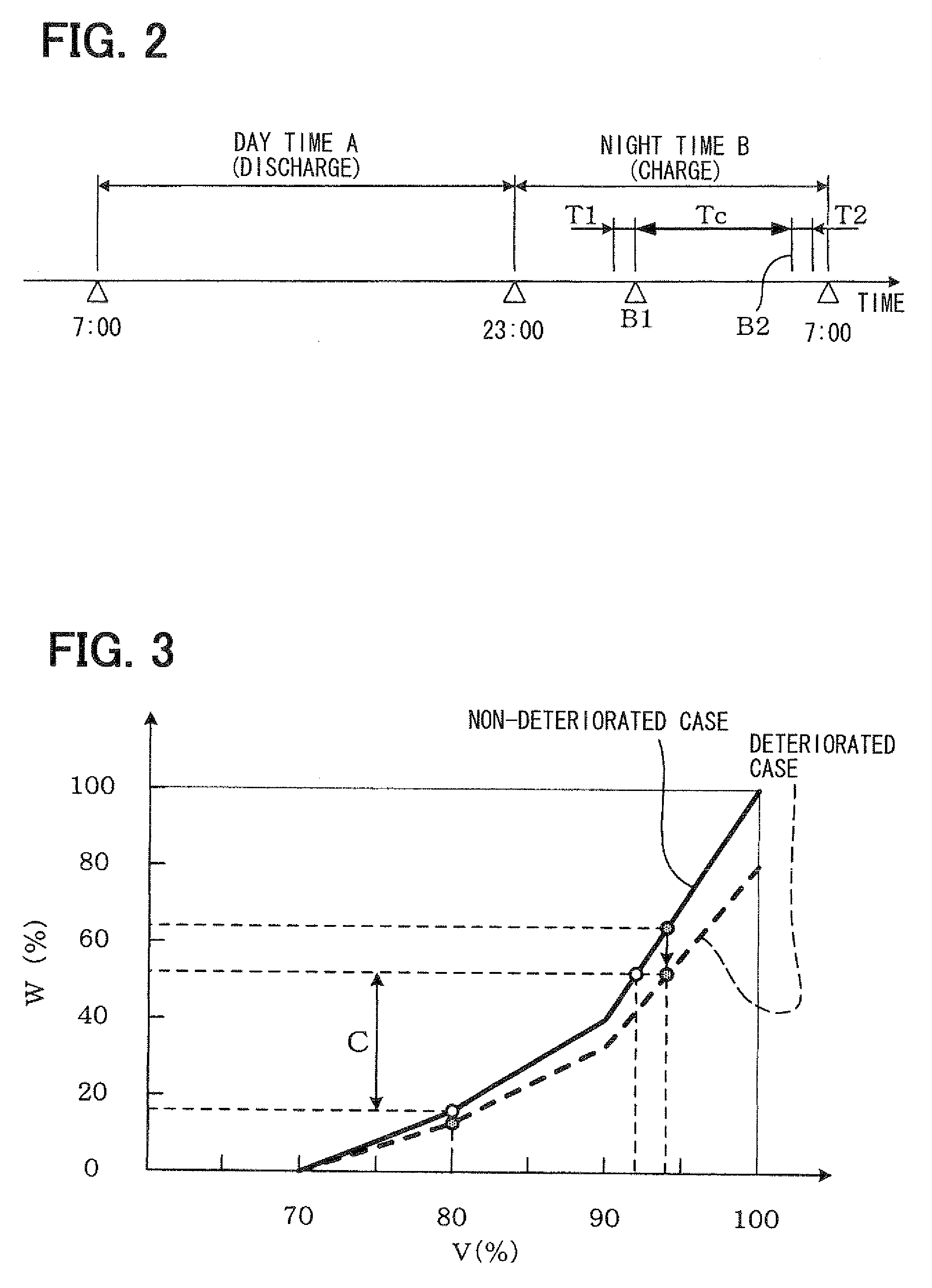
[0025]As shown in FIG. 2, the nighttime B is defined from 23:00 to 7:00, and the daytime A is defined from 7:00 to 23:00, for example. Electricity cost of the daytime A is calculated based on daytime rate, and electricity cost of the nighttime B is calculated based on nighttime rate. The charging control device 2 may be a computer including an electricity remaining amount detecting unit 21, a necessary charge amount calculating unit 22, a necessary charge period calculating unit 23, and a charging starting unit 24.

[0026]The electricity remaining amount detecting unit 21 detects an e...

second embodiment

[0083]A battery 3 is configured to be cooled by using cold energy emitted from a heat-pump hot water supplier 5, in a second embodiment. The supplier 5 is activated by receiving electricity from a utility power source 7 in nighttime B.

[0084]As shown in FIG. 8, the supplier 5 has a heat pump 51, a storage tank 52, a circulation pipe 53 and a controller 54. The controller 54 controls the supplier 5 to operate in nighttime B. Water Y1 flows into the tank 52, and is circulated in the pipe 53, due to a circulation pump 511.

[0085]Refrigerant X circulates in the heat pump 51, and heat transmission is performed by an evaporator 512 from air to refrigerant X. A temperature of the heated refrigerant X is further raised by a compressor 513. Heat is transmitted from refrigerant X to water Y1, due to a water-heat exchanger 514. Water Y1 is changed into hot water Y2 by the exchanger 514, and the hot water Y2 flows into the tank 52. In contrast, refrigerant X is cooled by the water Y1 in the excha...


PUM


Abstract

A charging control device for an electricity storage system includes a unit to detect an electricity remaining amount of a battery, a unit to calculate a necessary charge amount, a unit to calculate a necessary charge period, and a unit to start a charging from a charger to the battery at a start timing of nighttime. The start timing is defined to go back by the necessary charge period from a target timing, when the charging is defined to be finished at the target timing. The necessary charge amount is necessary for a following daytime, and is discharged for a load in the daytime.

Description

CROSS REFERENCE TO RELATED APPLICATION[0001]This application is based on Japanese Patent Application No. 2009-103978 filed on Apr. 22, 2009, the disclosure of which is incorporated herein by reference in its entirety.BACKGROUND OF THE INVENTION[0002]1. Field of the Invention[0003]The present invention relates to a charging control device and an electricity storage system.[0004]2. Description of Related Art[0005]Alternating voltage supplied from a utility power source is converted into direct-current voltage by a charger, and a home-use battery is charged by controlling the charger. Electricity is stored in the battery in nighttime, and the stored electricity is used in daytime, because electricity cost is low in nighttime.[0006]JP-B2-3827676 discloses an electricity storage system, and the system operates in a nighttime mode, a discharge mode, or a utility backup mode. In the nighttime mode, a battery of the system is charged by a utility power source, and nighttime rate is applied ...

Claims


Application Information

Patent Timeline
IPC IPC(8): H02J7/00H02J3/32H02J3/38
CPCH02J3/32Y04S20/222Y02B70/3225
Inventor SAKAKIBARA, HISAYOSHI
Owner DENSO CORP
Why Eureka
Try Eureka