Tool insert blanks and method of manufacture

Inactive Publication Date: 2010-10-28
CORBIN MFG
View PDF17 Cites 26 Cited by
  • Summary
  • Abstract
  • Description
  • Claims
  • Application Information

AI Technical Summary

Benefits of technology

[0007]The present invention provides tool insert blanks and methods of manufacturing tool insert blanks ha

Problems solved by technology

While this does not present undue problems with insets having a PCBN cutting edge, the grinding time

Method used


Image

  • Tool insert blanks and method of manufacture
  • Tool insert blanks and method of manufacture
  • Tool insert blanks and method of manufacture

Examples


Embodiment Construction

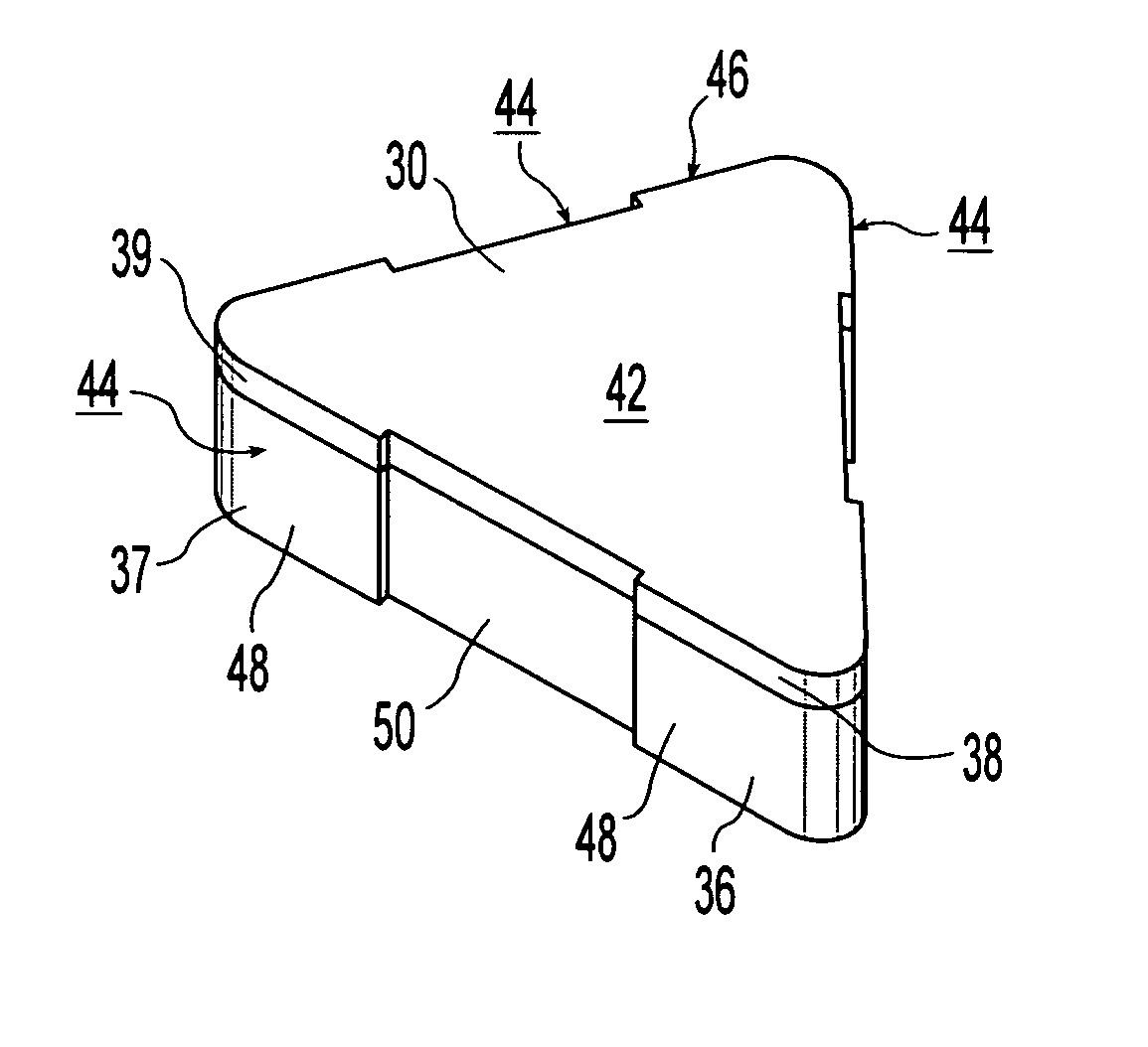
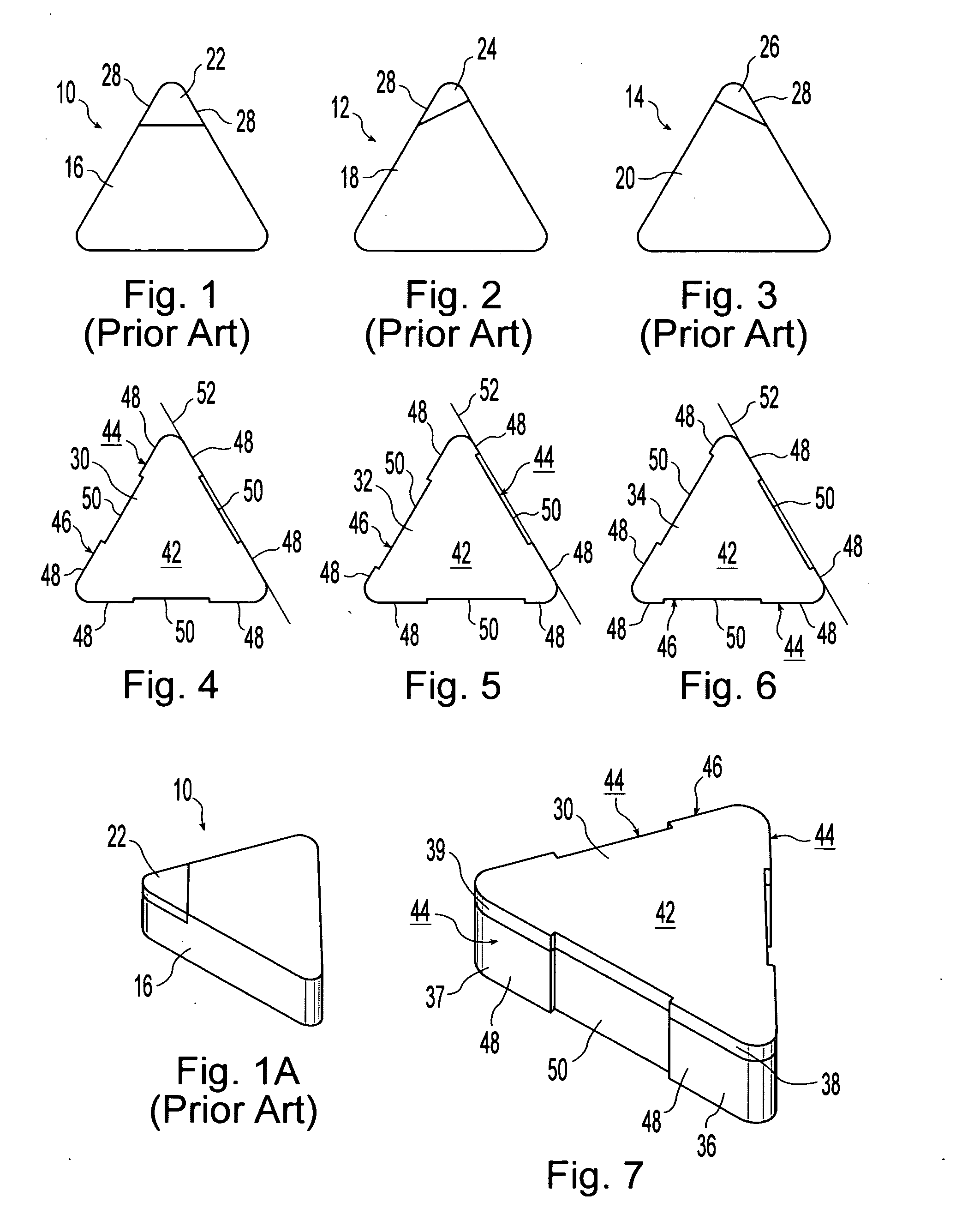
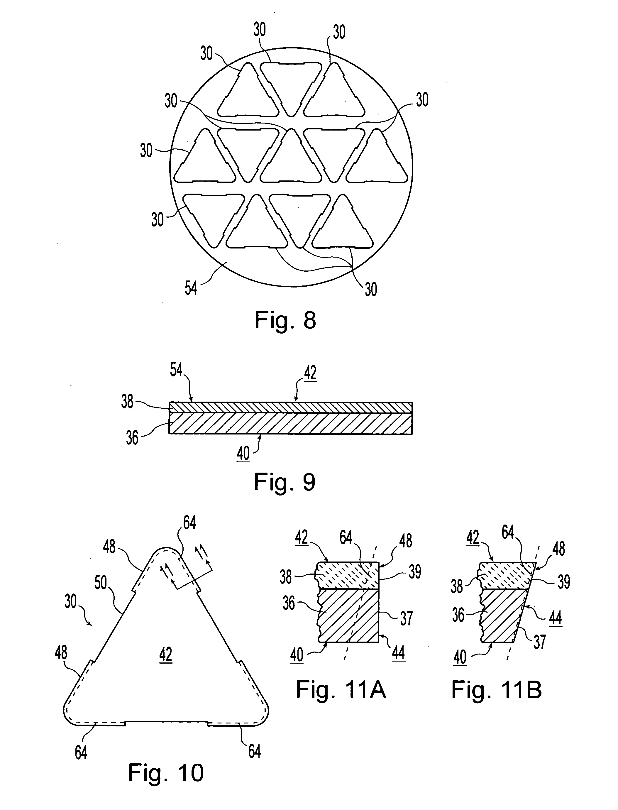
[0029]Three slightly different configurations of insert blanks 30, 32, 34 in accordance with the present invention are illustrated in FIGS. 4-6. Each of the blanks 30, 32, 34 includes a base layer 36 and a relatively harder layer 38. In the illustrated blanks, 30, 32, 34, base layer 36 is a cemented tungsten carbide layer and harder layer 38 is formed out of a PCD material. Other suitable materials may also be used to form layers 36, 38. For example, a PCBN material can be used to form the relatively harder layer 38. The base layer 36 and hard layer 38 of insert blank 30 are best seen in FIG. 7.

[0030]Two opposing sides of insert blanks 30, 32, 34 are defined by major surfaces 40, 42. In the illustrated embodiments, major surface 40 is formed by base layer 36 and major surface 42 is formed by hard layer 38 with both of the layers being oriented parallel with major surfaces 40, 42. A plurality of edge surfaces 44 extend between the two opposing major surfaces 40, 42 and define an oute...


PUM

PropertyMeasurementUnit
Angleaaaaaaaaaa
Perimeteraaaaaaaaaa

Abstract

A tool insert blank including first and second major surfaces and a plurality of edge surfaces defining an outer perimeter of the blank. A first layer defines the first major surface and a first portion of the plurality of edge surfaces proximate the first major surface. A second layer harder than the first layer is disposed substantially co-extensive with the second major surface and a second portion of the plurality of edge surfaces proximate the second major surface. At least one of the edge surfaces includes a projecting portion defining a first engagement plane and a recessed portion spaced inwardly of the engagement plane whereby the grinding wheel is engageable with the projecting portion without engaging the recessed portion. The second layer can be formed out of various materials including polycrystalline diamond and cubic boron nitride materials. A method of forming a tool insert blank is also disclosed.

Description

BACKGROUND OF THE INVENTION[0001]1. Field of the Invention[0002]The present invention relates to tool inserts such as a cutting insert used in machining operations, blanks for forming such tool inserts and a method of manufacture.[0003]2. Description of the Related Art[0004]Machining methods such as turning or milling require the use of cutting tools made from hard materials. Cemented tungsten carbide was developed many decades ago as a much harder alternative to steel. Cemented tungsten carbide may be brazed to a steel shank but it is more commonly employed as an “insert” that is attached to tool holder by clamping or by engaging a screw with a hole in the insert. Such inserts have an appropriate thickness and are provided in a variety of different geometries. Some of the more common insert geometries are triangular, square and rhombic inserts.[0005]More recently, polycrystalline cubic boron nitride (PCBN) and polycrystalline diamond (PCD) materials have been used with inserts to p...

Claims


Application Information

Patent Timeline
IPC IPC(8): B26D3/00B23P13/04
CPCB23B27/141Y10T29/49996B23B2200/128B23B2226/125B23B2226/315B23P13/04B23P15/28B24B1/00B24B3/343B24B7/22B23H7/02B23H9/00Y10T407/23Y10T407/26Y10T407/27B23B2200/125
Inventor CORBIN, LAWRENCE W.
Owner CORBIN MFG
Why Eureka
Try Eureka