
Multi stage radial compressor

a radial compressor and multi-stage technology, applied in the direction of machines/engines, stators, liquid fuel engines, etc., can solve the problems of secondary flow loss increase, incident flow loss, and unwanted flow loss

Inactive Publication Date: 2010-10-28
MAN ENERGY SOLUTIONS SA
View PDF7 Cites 42 Cited by
  • Summary
  • Abstract
  • Description
  • Claims
  • Application Information

AI Technical Summary

Benefits of technology

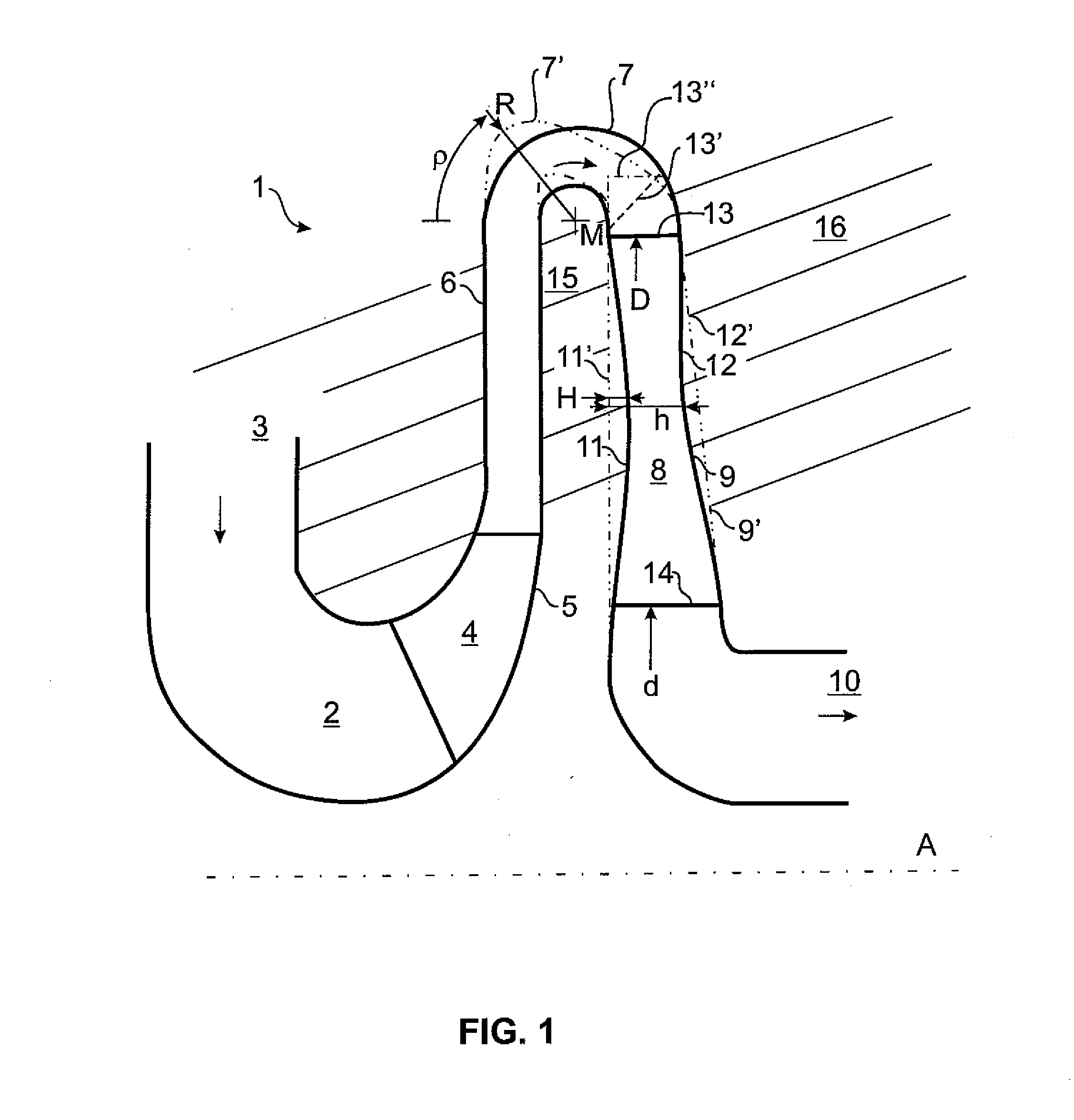
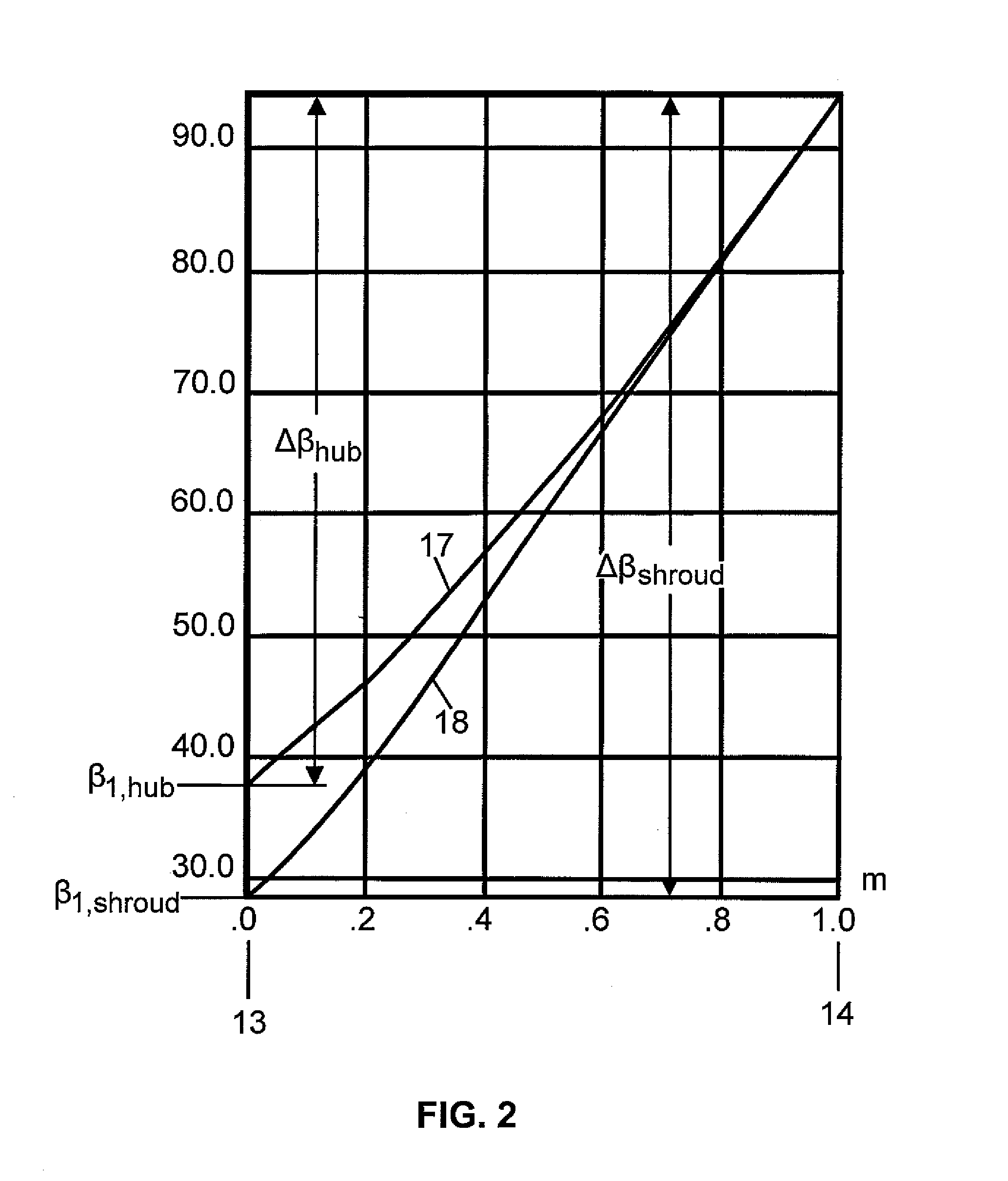
[0023]A three-dimensional vane shape manifesting itself in a twisting of the vane surface is generated by the uneven vane angle distribution at the vane head and vane base according to the invention. In this way, inhomogeneities in the flow angle distribution resulting from the impeller outlet flow of the upstream stage and / or the 180-degree bend of the curved deflecting channel can be reduced or compensated, which makes it possible to improve the incident flow of the downstream stage, reduce the flow incidence and improve the guidance of the flow. The efficiency of the radial compressor stage can advantageously be increased in this way. At the same time, the diffuser ratio can also be reduced, which makes it possible to reduce the structural dimensions of the entire radial compressor.
[0026]A first vane outlet angle at the vane head is preferably substantially identical to a second vane outlet angle at the vane base. Vane outlet angle refers to the vane angle at the downstream rear area of the vane, i.e., in the area in which the flow exits the vane. In this way, a two-dimensional, untwisted vane is advantageously realized at the vane outlet, which improves the incident flow of the downstream compressor stage. The vane outlet angles can range between 80° and 100°, for example, particularly between 85° and 95°, and amount substantially to 90° in a preferred embodiment.
[0035]The ratio between the outer diameter and inner diameter is preferably less than or equal to 1.6, particularly less than or equal to 1.55. The different vane angle distribution according to the invention and the resulting reduction in incidence losses and secondary flow losses permits formation of the radial installation space of the radial compressor without excessive losses.

Problems solved by technology

Particularly at higher volume flows, the flow angle distribution at the entrance of a 180-degree bend between two stages of the compressor is very uneven as a result of the impeller outlet flow, which leads to severe faulty inlet flows in the previously known 2D return blading and, therefore, to unwanted flow losses.
If the diffuser ratio is decreased in order to achieve smaller structural dimensions, the incident flow losses and secondary flow losses increase.

Method used


Image

  • Multi stage radial compressor
  • Multi stage radial compressor
  • Multi stage radial compressor

Examples


Embodiment Construction

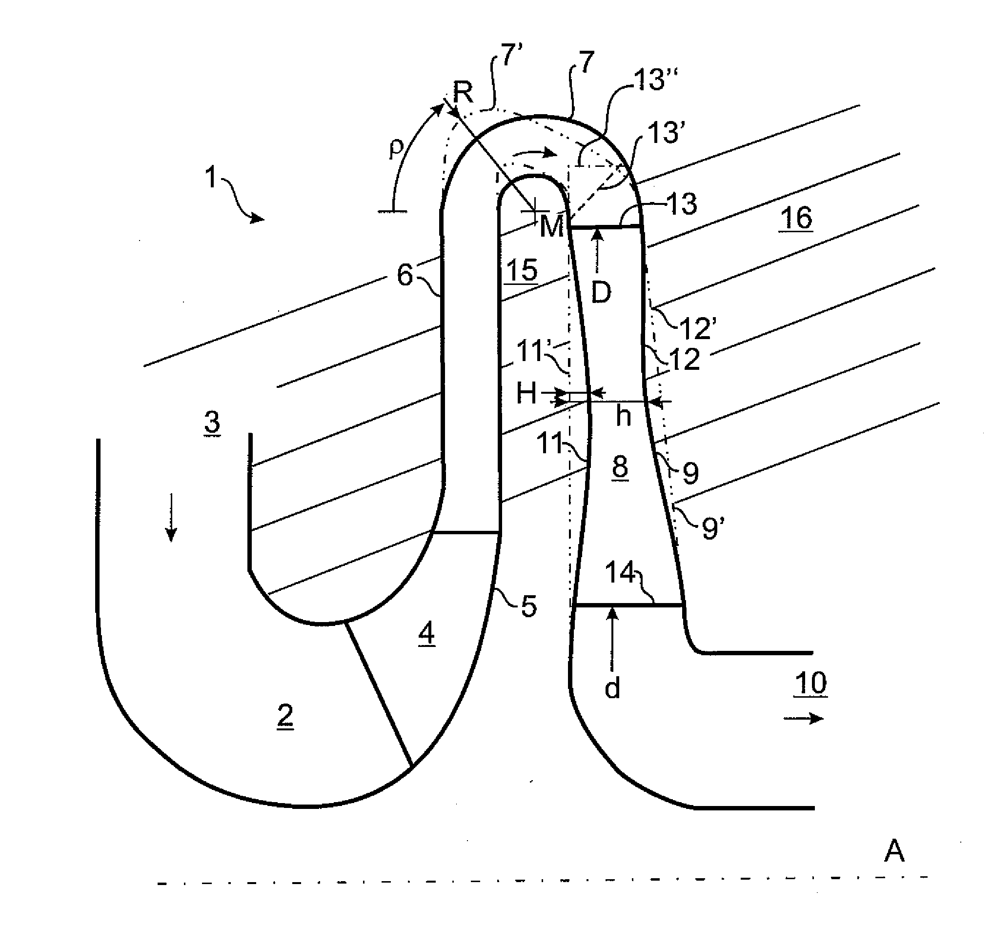
[0042]FIG. 1 shows the meridional section of a radial compressor stage of a multistage radial compressor 1 in a first embodiment of the present invention (solid lines) and in another embodiment of the present invention (dash-double-dotted line). It can be seen that the flow channel 2 comprises a stage inlet 3. A fluid to be compressed which is conveyed, for example, from another, upstream radial compressor stage (not shown) flows into this stage inlet 3. The flow direction is indicated by arrows.

[0043]An impeller 4 comprising a plurality of impeller vanes 5 is arranged in a first lower bend of the flow channel 2. The impeller 4 is connected to a driveshaft, not shown, so as to be fixed with respect to rotation relative to it and is rotated by this driveshaft around an axis of rotation or longitudinal axis A. Downstream of the impeller 4, the fluid reaches a diffuser portion 6 adjoined by a curved deflecting channel 7 which substantially forms a 180-degree bend.

[0044]In the embodimen...


PUM


Abstract

A multistage radial compressor (1) with at least two compressor stages for compressing a fluid has a compressor housing (16) in which a flow channel (2) is formed for the fluid to be compressed; an impeller (4) with a plurality of impeller vanes (5) which are arranged in the flow channel (2) and are rotatable with the impeller (4) around a driveshaft (A), and a 3D return blading (8) with a plurality of return vanes (9) which are fixed with respect to rotation relative to the compressor housing (16). The flow channel (2) has a curved deflecting channel (7) which is arranged in front of the return vanes (9) in the flow direction. A vane base (11) and / or, axially downstream thereof, a vane head (12) of the return vanes (9) of the 3D return blading (8) have / has a curvature, and / or the return vanes (9) have a first vane angle distribution (17) at the vane base (11) and a second vane angle distribution (18) differing from this at the vane head (12).

Description

BACKGROUND OF THE INVENTION[0001]1. Field of the Invention[0002]The present invention is directed to a multistage radial compressor for compressing in particular gaseous fluids.[0003]2. Description of the Related Art[0004]The compressor of the present invention includes a housing in which a flow channel is formed for the fluid to be compressed, an impeller with a plurality of impeller vanes which are arranged in the flow channel and are rotatable with the impeller around a driveshaft, and 3D return blading with a plurality of return vanes which are fixed with respect to rotation relative to the compressor housing. The flow channel has a curved deflecting channel which is arranged in front of the return vanes in the flow direction.[0005]A radial compressor of the type mentioned above is known, for example, from DE 42 34 739 C1 corresponding to U.S. Pat. No. 5,490,760, DE 196 54 840 A1, DE 34 30 307 A1 corresponding to U.S. Pat. No. 4,579,509, and DE 195 54 840 A1.[0006]Particularly a...

Claims


Application Information

Patent Timeline
Patent Type & Authority Applications(United States)
IPC IPC(8): F01D25/00
CPCF04D29/444F04D17/122F05D2250/70
Inventor RICHTER, FRANZ-ARNOVOSS, HEINRICHHILDEBRANDT, ANDREJAKIEL, CHRISTOPH
Owner MAN ENERGY SOLUTIONS SA
Learn More