
Dust-Proof and Anti-Oil Leakage Structure for a Fan

a technology of dust-proof and anti-oil leakage structure and fan, which is applied in the direction of positive displacement liquid engine, piston pump, liquid fuel engine, etc., can solve the problems of large noise and short service life, and achieve the effect of long service life and low nois

Inactive Publication Date: 2010-10-28
POWER LOGIC TECH DONGGUAN
View PDF9 Cites 30 Cited by
  • Summary
  • Abstract
  • Description
  • Claims
  • Application Information

AI Technical Summary

Benefits of technology

[0006]The primary objective of the present invention is to provide a dust-proof and anti-oil leakage structure for a direct current brushless cooling fan, which can effectively solve the drawbacks of the existing fans.
[0024]Due to improvements to the dust-proof and anti-oil leakage structure and increase of the dust-proof and anti-oil leakage parts, the present invention has the following advantages such as fine dust-proof and anti-oil leakage effect, lower noise, long service life, etc.

Problems solved by technology

Due to an unreasonable dust proof and anti-oil leakage structure, dust is prone to entering the interiors of the stator and bearings, and lubricant is prone to being thrown out, thus causing many drawbacks such as large noise, short service life, etc.

Method used


Image

  • Dust-Proof and Anti-Oil Leakage Structure for a Fan
  • Dust-Proof and Anti-Oil Leakage Structure for a Fan
  • Dust-Proof and Anti-Oil Leakage Structure for a Fan

Examples


Embodiment Construction

[0042]The present invention will be clearer from the following description when viewed together with the accompanying drawings, which show, for purpose of illustrations only, the preferred embodiment in accordance with the present invention.

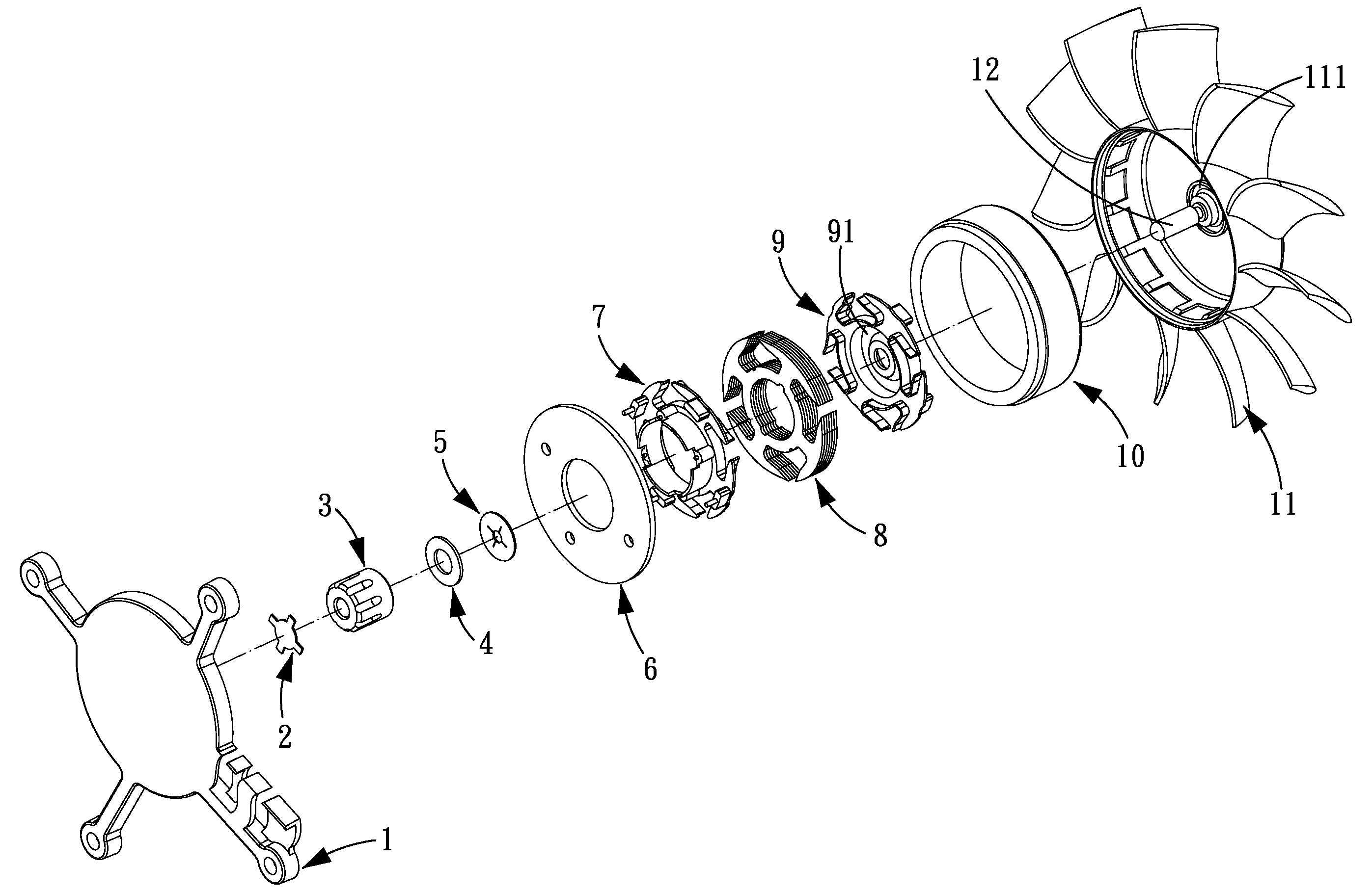
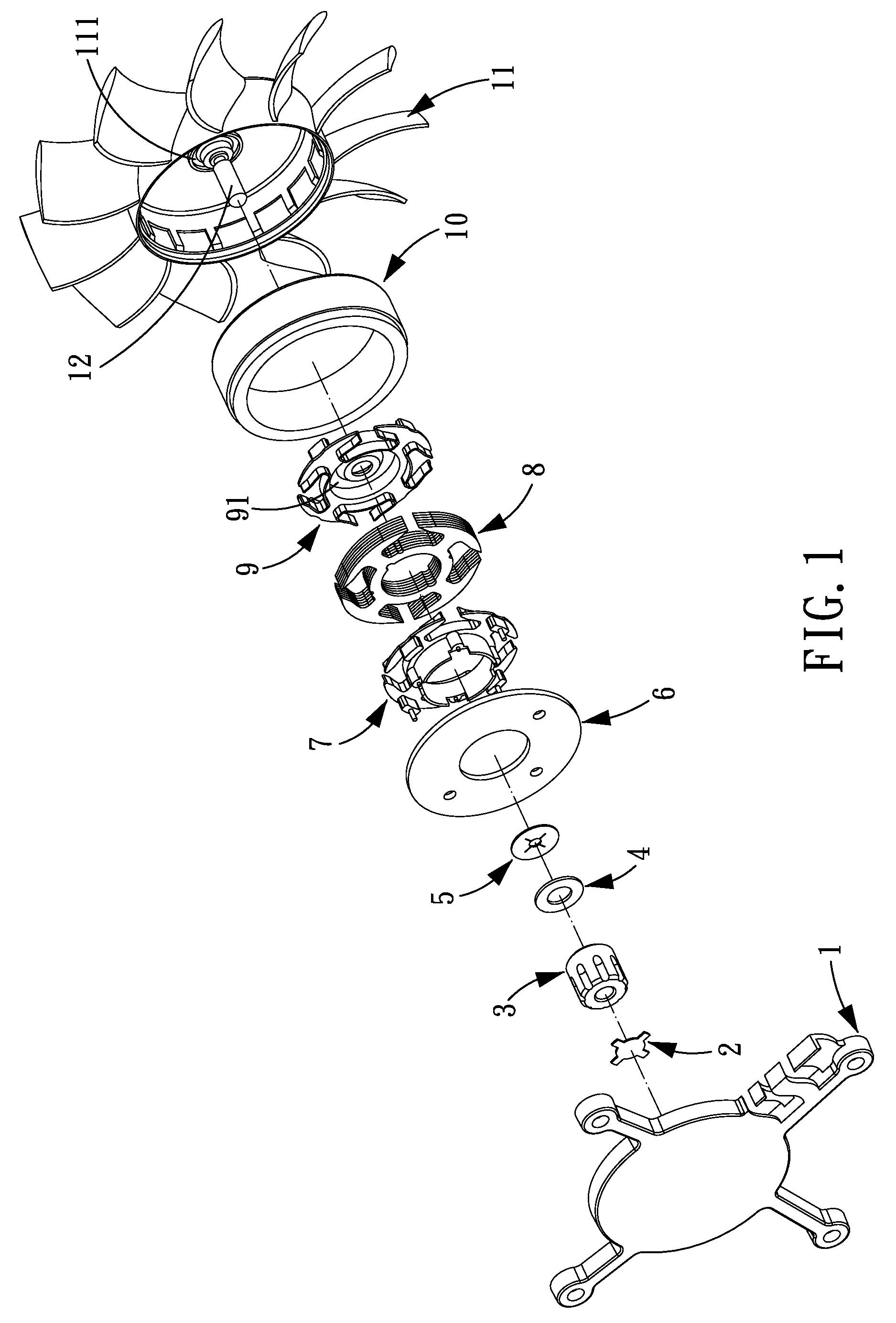
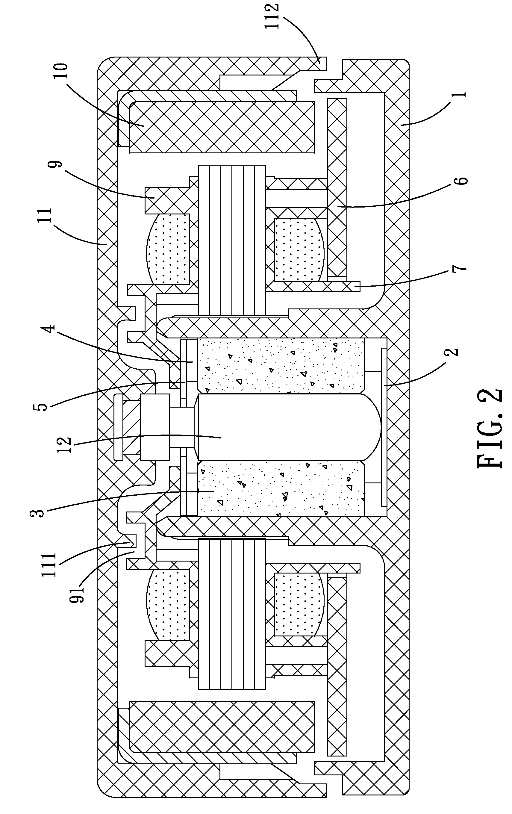
[0043]Referring to FIGS. 1-2, a dust-proof and anti-oil leakage structure for a fan in accordance with the present invention comprises a blade assembly 11, an outer frame 1, a spindle 12, a magnet frame assembly 10, an upper insulating cover 9, a silicon steel lamination 8, a lower insulating cover 7, a PCB (printed circuit board) heat sink 6, an elastic gasket 5 with a cross hole, a washer 4, a copper sleeve 3 and a cross-shaped elastic gasket 2.

[0044]The outer frame 1 has a bottom completely sealed to avoid oil leakage and adopts the down-draft design to keep the height of the product constant whenever the product is put on its side or upside down, avoiding many problems of the conventional structure which is assembled by using the magnetic sus...


PUM


Abstract

A dust-proof and anti-oil leakage structure for a fan comprises a blade assembly, an outer frame and a center stator. On a spindle between the blade assembly and the outer frame are installed in sequence an outer frame, an upper insulating cover, a silicon steel lamination, a lower insulating cover, a printed circuit board heat sink, an elastic gasket with a cross hole, a washer, a copper sleeve, a round elastic gasket.

Description

BACKGROUND OF THE INVENTION[0001]1. Field of the Invention[0002]The present invention relates to a fan; and more particularly to a dust proof and anti-oil leakage structure for a direct-current brushless cooling fan.[0003]2. Description of the Prior Art[0004]A conventional direct-current brushless cooling fan essentially comprises a blade assembly, an outer frame and a center stator. Due to an unreasonable dust proof and anti-oil leakage structure, dust is prone to entering the interiors of the stator and bearings, and lubricant is prone to being thrown out, thus causing many drawbacks such as large noise, short service life, etc.[0005]The present invention has arisen to mitigate and / or obviate the afore-described disadvantages.SUMMARY OF THE INVENTION[0006]The primary objective of the present invention is to provide a dust-proof and anti-oil leakage structure for a direct current brushless cooling fan, which can effectively solve the drawbacks of the existing fans.[0007]In order to...

Claims


Application Information

Patent Timeline
IPC IPC(8): F04D25/08H02K5/10
CPCF04D29/063F04D25/0626F04D25/0646F04D25/064
Inventor HSU, VICENTLIN, JACKLIU, XUELIANG
Owner POWER LOGIC TECH DONGGUAN
Learn More