Sink With Storage Rack Assembly

Inactive Publication Date: 2010-11-04
KOHLER CO
View PDF19 Cites 17 Cited by
  • Summary
  • Abstract
  • Description
  • Claims
  • Application Information

AI Technical Summary

Benefits of technology

[0019]Thus, a consumer is provided with an option to affix an accessory storage rack without using up valuable storage space on th

Problems solved by technology

Garbage disposals can be a significant source of vibration transmitted through the sink assembly.
However, the floor s

Method used


Image

  • Sink With Storage Rack Assembly
  • Sink With Storage Rack Assembly
  • Sink With Storage Rack Assembly

Examples


Example

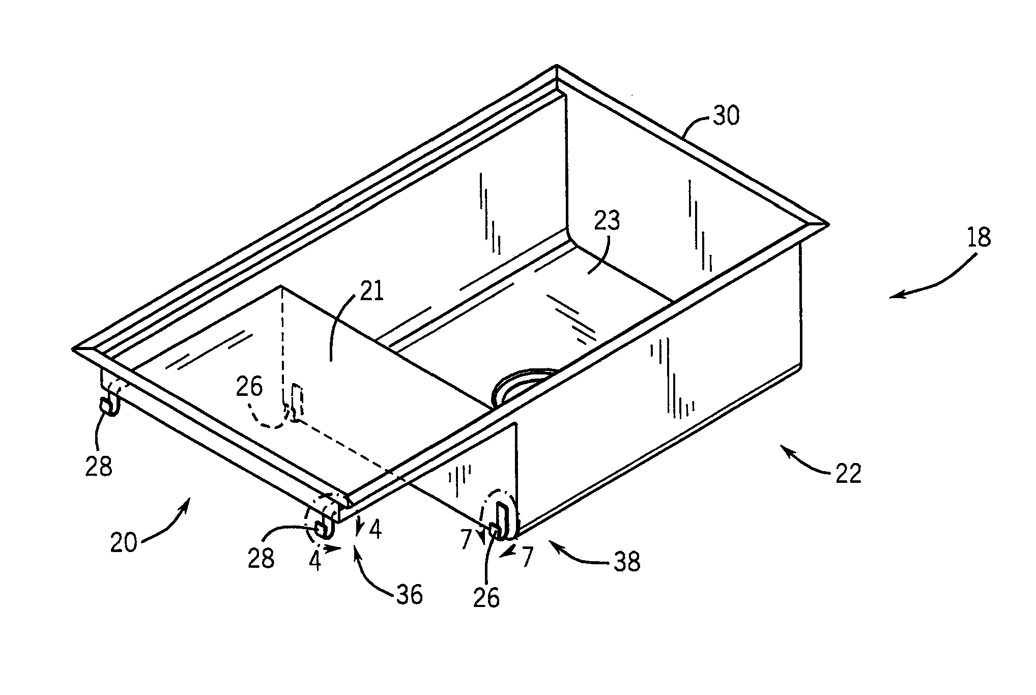
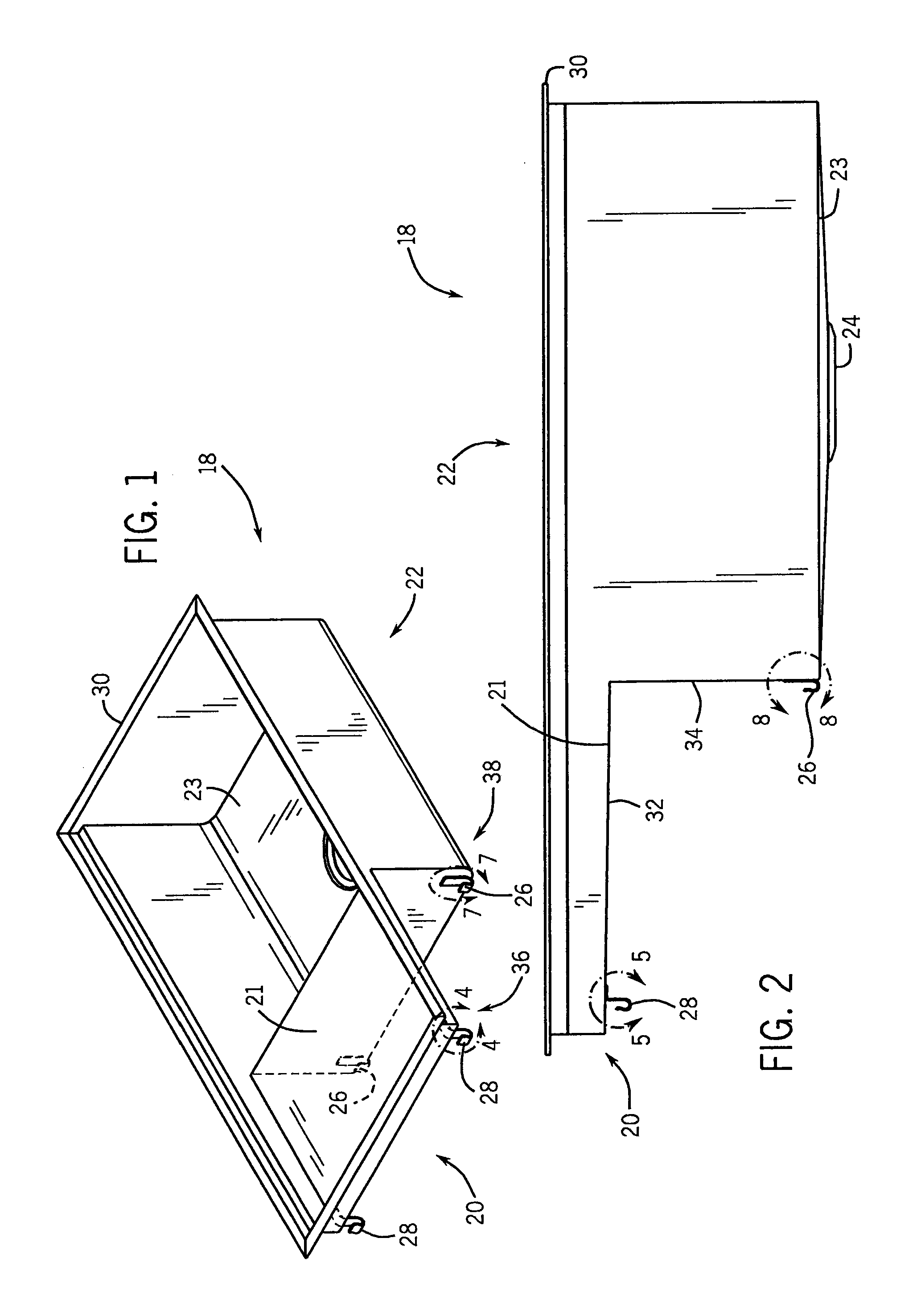
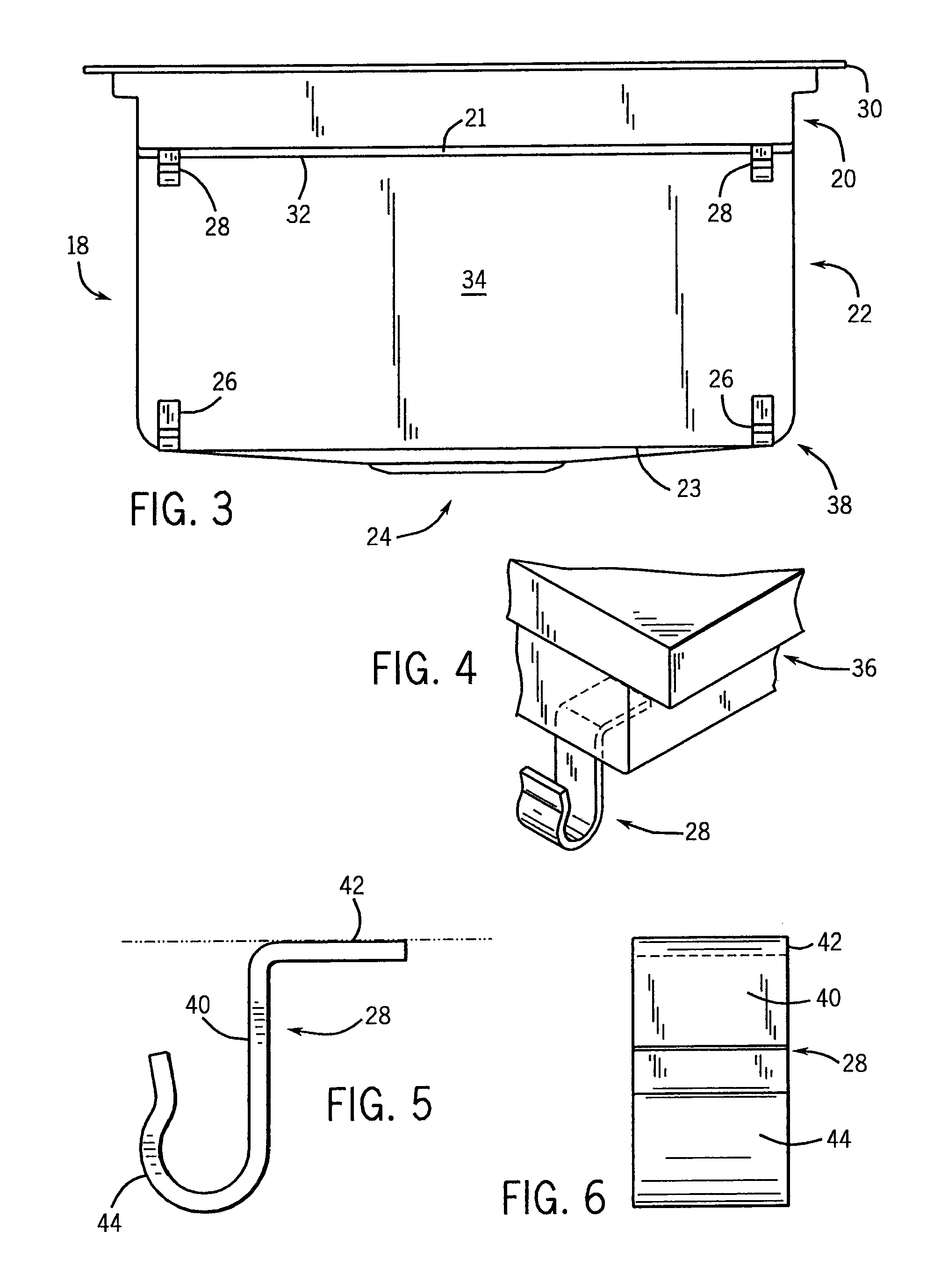
[0036]Referring first to FIGS. 1-3, there is shown a sink 18 of the present invention which contains a sink basin 22 that is substantially rectangular in shape. The sink basin has a bottom surface 23 containing the usual drainage hole 24 for draining liquids and other materials held in the sink basin 23. A garbage disposal (not shown) may be installed underneath the drainage hole 24 to grind up any waste materials held in the sink basin 22.

[0037]A work / drain area 20 is integral to the sink basin 22 and extends (in this embodiment) to the left of the sink basin 22. The surface of the work area 21 is substantially flat and is substantially higher than the bottom surface of the sink basin 23, facilitating the easy transfer of liquids and waste materials from the work area 20 to the sink basin 22.

[0038]The sink 18 further has four spring clips 26, 28 mounted on the assembly 18. Two of the spring clips are side mounted spring clips 26, which are mounted to the left side exterior surface ...


PUM


Abstract

A combined sink and storage rack assembly is disclosed. The assembly includes a sink basin, a work area integral with the sink basin, and a wire rack hung underneath the work area at a side of the basin. Spring clips mounted on the sink basin and work area hook the rack. Sections of the rack's wire that insert into the spring clips are coated with an elastomer, such as silicone rubber, in order to dampen vibrations transmitted from the sink.

Description

CROSS-REFERENCE TO RELATED APPLICATION[0001]This application claims priority based on U.S. provisional application 61 / 174,003 filed Apr. 30, 2009.STATEMENT OF FEDERALLY SPONSORED RESEARCH OR DEVELOPMENT[0002]Not applicable.BACKGROUND OF THE INVENTION[0003]The present invention relates to sinks having a storage rack depending there from for holding varied accessories useful with the sink. More particularly, it relates to such assemblies provided with means to dampen vibrations transmitted through the sink basin.[0004]Typically sinks have a basin for holding water, with a drainage hole for draining the water at the bottom. Sinks additionally contain upper rims extending outward. There sometimes is also a substantially flat work / drain area integral with the basin at its side.[0005]The drainage hole at the bottom of the basin is connected to a sewer pipe. Often, a garbage disposal is installed between the drainage hole and sewer pipe to grind up waste. Garbage disposals can be a signifi...

Claims


Application Information

Patent Timeline
IPC IPC(8): E03C1/18
CPCE03C1/186
Inventor MILLER, JASON R.EILMUS, NIELS J.
Owner KOHLER CO
Why Eureka
Try Eureka