Pipe scanner

a scanner and pipe technology, applied in the field of pipe scanners, can solve problems such as major environmental concerns, and achieve the effect of convenient interchang

Active Publication Date: 2010-11-04
WESTINGHOUSE ELECTRIC CORP
View PDF8 Cites 65 Cited by
  • Summary
  • Abstract
  • Description
  • Claims
  • Application Information

AI Technical Summary

Benefits of technology

[0007]In one embodiment, the drive surface of the axial drive is at least one wheel and, preferably, the wheel is magnetized to gain traction on ferrous piping. Preferably, the drive surface comprises at least two wheels with each wheel spaced from the other around the circumference of the pipe. In the embodiment in which the axial drive has at least two drive surfaces that are circumferentially spaced from each other, a first motor operates a first of the drive surfaces and a second motor operates a second of the drive surfaces and the first and second motors are synchronized. Optionally, a wheel support assembly is attached at one end to the first motor and at a second end around the pipe to the second motor with an idler wheel extending off the wheel support assembly toward the pipe, substantially midway between the first and second motors. Desirably, means are provided for remotely moving the idler wheel towards and away from engagement with the pipe. Preferably, the wheel support assembly includes a wheel housing, attachment arms that extend out from either side of the wheel housing and attachment brackets that extend from the distal ends of the attachment arms, wherein the attachment arms are coupled to the wheel housing with a quick disconnect. The quick disconnect enables the attachment arms to be easily interchanged with attachment arms of another configuration to accommodate different diameter piping.

Problems solved by technology

A leak in the Alaskan oil pipeline caused a major environmental concern that necessitated the shutdown of the Alaskan oil pipeline for a considerable period.

Method used


Image

  • Pipe scanner
  • Pipe scanner
  • Pipe scanner

Examples


Embodiment Construction

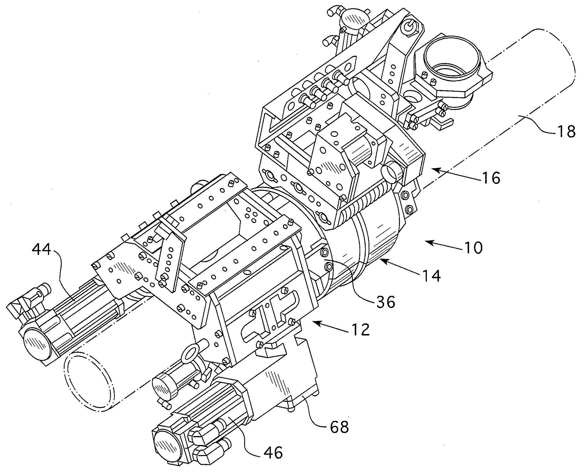
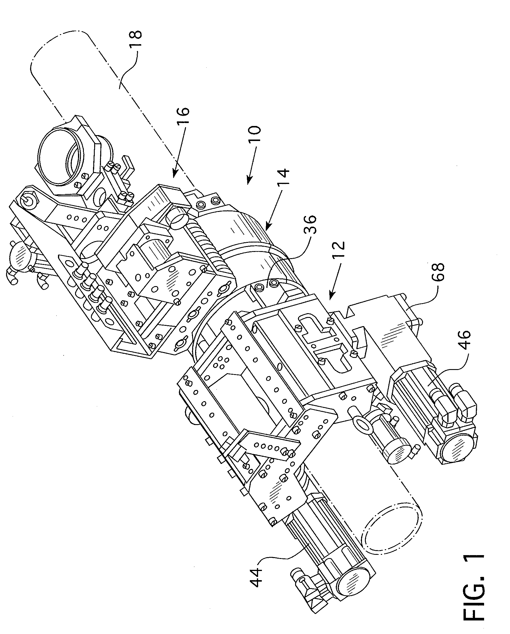
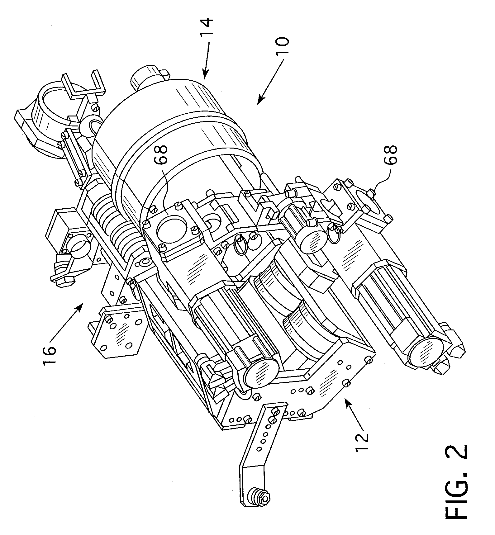
[0019]Typically, pipe scanners with a an axial drive are supported by a fixed arm on which they move in the axial direction. The fixed arm is cantilevered over the pipe parallel with the axis of the pipe and generally limits the axial movement of the scanner to approximately a 24 inch (61 cm.) stroke. In such an arrangement, after completing a 360° circumferential scan, the scanner has to be manually relocated on the pipe to the next 24 inch (61 cm.) interval (less when compensating for overlap to guarantee 100% coverage). The scanner of this invention overcomes that limitation and provides a modular design that can be used on varying sized pipe. The scanner is capable of traveling axially along the pipe at 20 inches (50.8 cm.) per second and does not need to be removed except when negotiating a riser or vertical support member. In the case of the Alaskan Pipeline, the vertical support members may be approximately 60 feet (18.3 m.) apart. Thus, in such an application the scanner of ...


PUM

PropertyMeasurementUnit
axial movementaaaaaaaaaa
lengthaaaaaaaaaa

Abstract

A pipe scanner for non-destructively scanning an extended length of the circumference of a pipe along an axial dimension. The pipe scanner includes a collar sized to fit around the outer circumference of the pipe. Wheels supported on the collar ride on the surface of the pipe while maintaining a space between the inner surface of the collar and the outer surface of the pipe. A track extends circumferentially around the collar for guiding a circumferential drive unit that rides on the track and carries a non-destructive sensor for monitoring the surface of the pipe as the circumferential drive unit moves around the track. An axial drive unit is connected to the collar, having a plurality of circumferentially spaced drive wheels in contact with the pipe for moving the collar along the extended length.

Description

BACKGROUND OF THE INVENTION[0001]1. Field of the Invention[0002]This invention pertains generally to pipe scanners for the non-destructive examination of piping and, more particularly, to such scanners that can continuously scan the 360° circumference of a pipe over an extended length.[0003]2. Description of Related Art[0004]A leak in the Alaskan oil pipeline caused a major environmental concern that necessitated the shutdown of the Alaskan oil pipeline for a considerable period. As a result, a scanner was developed to continuously monitor the condition of the pipeline to avoid a similar catastrophe in the future. The scanner developed for the Alaskan Pipeline was designed for a 34 inch (86.36 cm.) diameter pipe and only would scan the lower half of the pipe. Typically, pipe scanners are limited to a 24 inch (60.96 cm.) stroke, i.e., the distance they can travel along a pipe without human intervention. After completing a 24 inch (60.96 cm.) stroke they would need to be manually relo...

Claims


Application Information

Patent Timeline
Patent Type & Authority Applications(United States)
IPC IPC(8): G01N29/04G01M99/00
CPCF17D5/00G01N2291/2634G01N29/265G01N29/225
Inventor ROBERTS, DOUGLAS J.
Owner WESTINGHOUSE ELECTRIC CORP
Why Eureka
Try Eureka