
Gear shift arrangement for a vehicle

a gear shift arrangement and vehicle technology, applied in the direction of mechanical equipment, transportation and packaging, cycles, etc., can solve the problems of reducing the performance and life of the cvt belt, generating a great deal of heat, and many atvs have a fairly complicated shift pattern, so as to facilitate and preferably accelerate the gear shi

Inactive Publication Date: 2010-11-04
HUSQVARNA AB
View PDF2 Cites 13 Cited by
  • Summary
  • Abstract
  • Description
  • Claims
  • Application Information

AI Technical Summary

Benefits of technology

[0008]At least one of the above mentioned objects and / or problems are met by providing a gear shift arrangement in accordance with the invention having the characteristics appearing from the appended claims. The gear shift arrangement according to the invention is thus essentially characterised in that the first set of gears are shiftable under influence of a first shift lever, that the positions of the second set of gears are shiftable under influence of a second shift lever (8) separate from the first one, and each shift lever is movable in essentially only one plane. Accordingly there are two separate shift levers and each lever is movable in only one plane, i.e. the shift lever will be moved in only one direction during a shift. With a conventional H pattern the lever will often have to be moved in three different directions, e.g. when rocking the vehicle. In a preferred embodiment each shift lever is movable in only a longitudinal plane of the vehicle. Further the two gear levers are arranged in a side by side arrangement on the vehicle close two each handgrip, so one is intended to be operated with the left hand, normally the second lever, and the other with the right hand, normally the first lever.

Problems solved by technology

During operation, such transmissions generate a great deal of heat.
Due to the nature of the CVT, heat can decrease performance and life of the CVT belt.
Many ATVs have a fairly complicated shift pattern for the shift lever of their shiftable manual gearbox.
Considering the bumpy ride of an off road vehicle in the terrain it can be fairly difficult to move the shift lever in an H pattern gear change system.
It is hard to move the shift lever from one corner of the H pattern over to another corner.
This loss of speed often makes the rocking less effective.
This can be annoying especially in bumpy terrain.

Method used


Image

  • Gear shift arrangement for a vehicle
  • Gear shift arrangement for a vehicle
  • Gear shift arrangement for a vehicle

Examples


Embodiment Construction

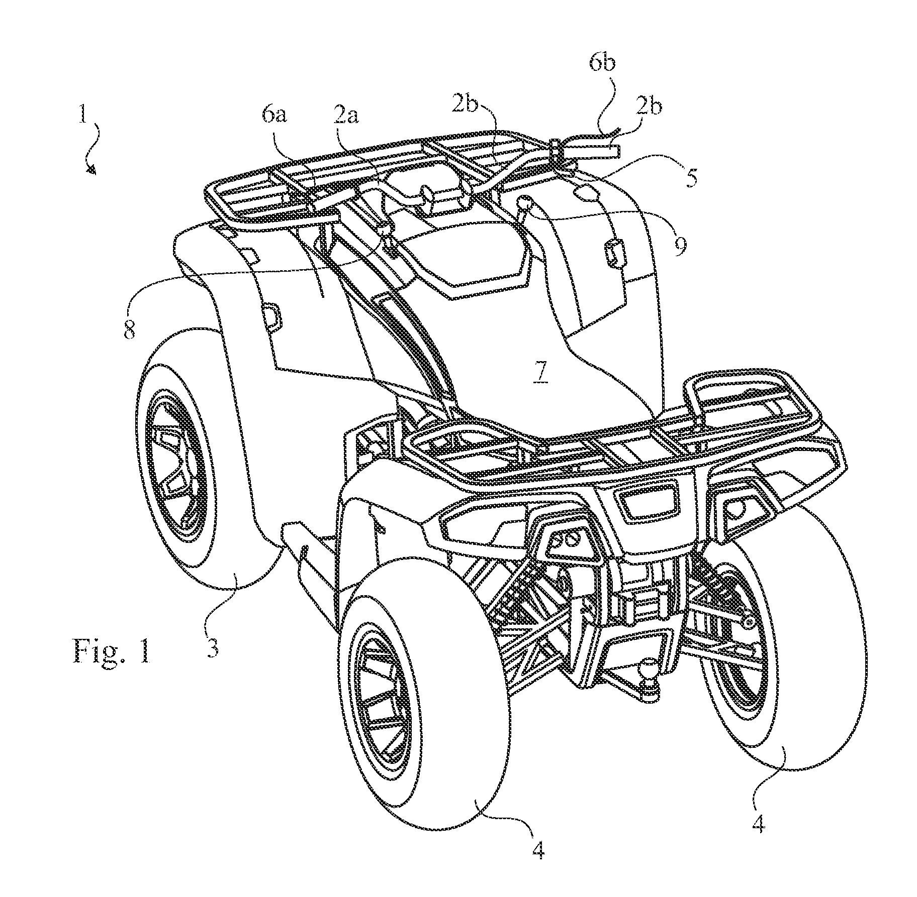
[0017]FIG. 1 shows a perspective view of an All Terrain Vehicle 1 (ATV). The ATV 1 has four wheels, front wheels 3 and rear wheels 4, a seat 7 to be straddled by an operator, and handlebars 2a, 2b for steering control. Further there are two gear shift levers 8,9, a first lever 9 and a second lever 8 located in a side by side configuration, i.e. left and right, preferably with a distance of several times the height of each lever.

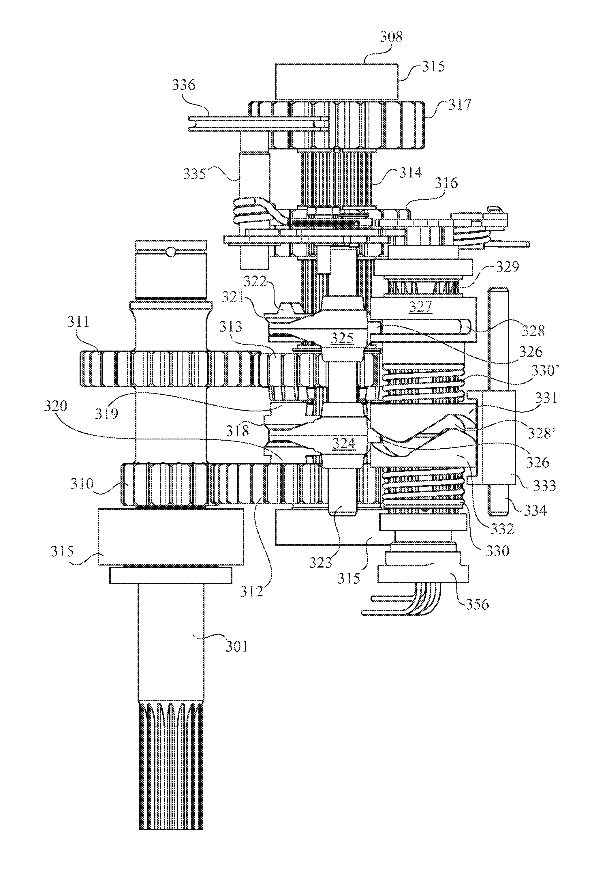
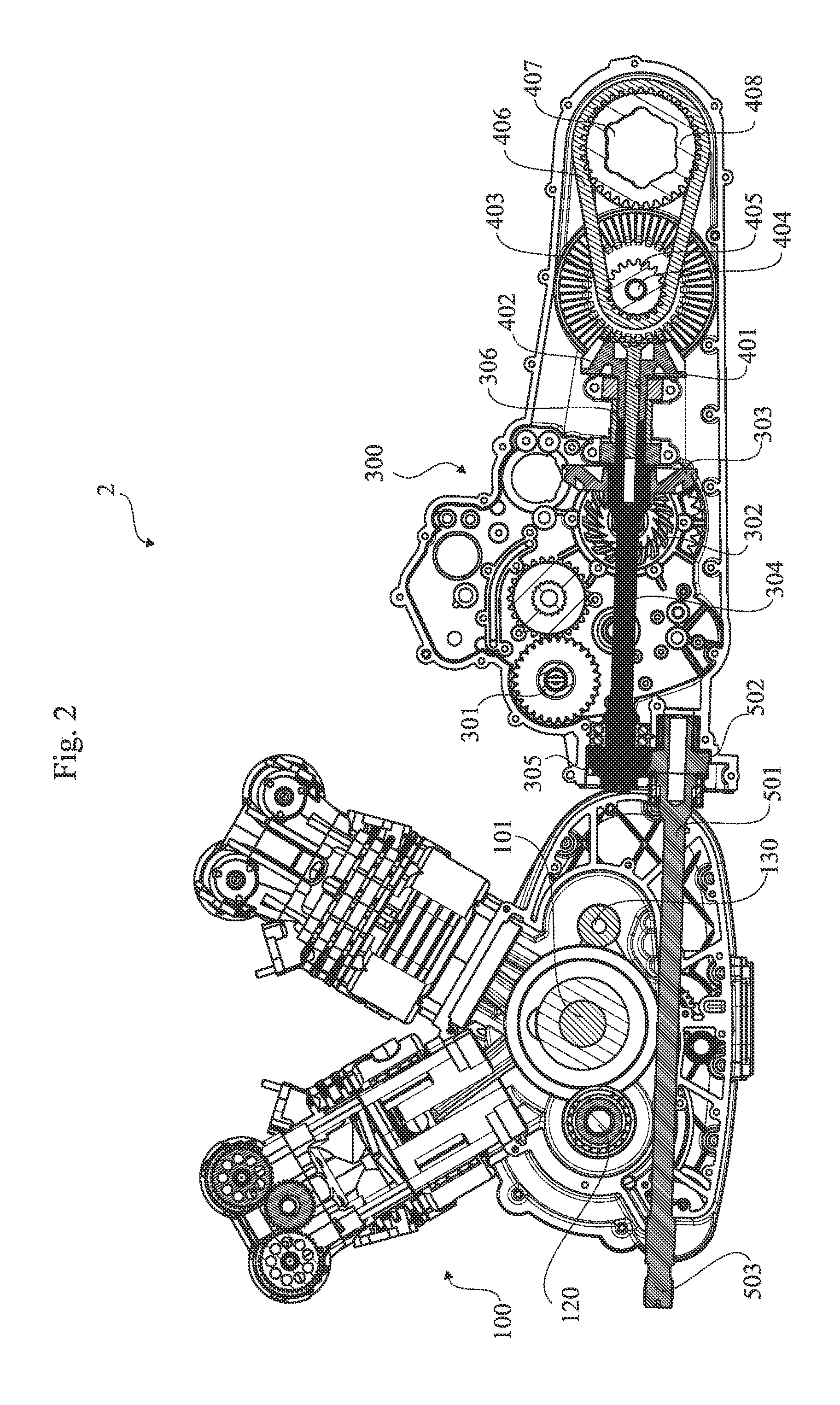
[0018]The power train 2 of the ATV will now be described with reference to FIGS. 2 and 3. The centre line of the powertrain is indicated by the longitudinal axis 10 providing a first lateral side 1, i.e. the right side of the power train, a second lateral side 12, i.e. the left side of the power train. The power train 2 with longitudinal axis 10 runs in a roughly longitudinal direction of the vehicle. In general, an internal combustion engine 100 (in FIGS. 3 and 4 only the connecting rods 102 of the engine 100 are shown) has an engine drive shaft 120 driving ...


PUM


Abstract

Gear shift arrangement for a shiftable manual gearbox (300) provided in a vehicle, e.g. an off road vehicle, scooter or snowmobile, comprising a shift operating mechanism (9, 8) to be operated by a driver, said gearbox having a first set of gears with positions for high speed, and at least one further gear from the group of gears low speed, neutral and parking, and a second set of gears with positions for at least forward and reverse. The positions of the first set of gears are shiftable under influence of a first shift lever (9), that the positions of the second set of gears are shiftable under influence of a second shift lever (8) separate from the first one, and each shift lever is movable in essentially only one plane.

Description

TECHNICAL FIELD[0001]The invention relates to a gear shift arrangement for a manual shiftable gearbox provided in a vehicle, e.g. an off road vehicle, scooter or snowmobile, comprising a shift operating mechanism to be operated by a driver, said gearbox having a first set of gears with positions for high speed, and at least one further gear from the group of gears low speed, neutral and parking, and a second set of gears with positions for at least forward and reverse.[0002]The invention also relates to a gear shift arrangement in which the shifting of the driver is transferred into turning of at least one shift control shaft that has a number of rotationally fixed shift sleeves each sleeve comprising at least a part of a shift groove that affects a control pin of a shift fork to make the shift fork move and axially move a shift ring that is rotationally fixed on a shaft of the gearbox and thereby make teeth of the shift ring engage / disengage with / from teeth of a gear wheel thereby ...

Claims


Application Information

Patent Timeline
Patent Type & Authority Applications(United States)
IPC IPC(8): F16H59/04
CPCB62K5/01F16H59/02Y10T74/2014F16H2312/08F16H2059/0239F16H63/18
Inventor PENTTILA, HEIKKIFRIEDRICHS, THOMAS
Owner HUSQVARNA AB
Learn More