Method and Device for Adjusting a Seat

Active Publication Date: 2010-11-04
BAYERISCHE MOTOREN WERKE AG
View PDF43 Cites 53 Cited by
  • Summary
  • Abstract
  • Description
  • Claims
  • Application Information

AI Technical Summary

Benefits of technology

[0065]Embodiments of the invention enable the automatic adjustment of a seat position that is ergonomic for the user of the seat without requiring the user to know or learn the adjustment possibilities of the seat. Likewise, the user need not know the seat position that would be advantageous from ergonomic aspects.
[0066]It is thus possible to automatically adjust a seat position for the user which enables high level of seat comfort over a long period of time.
[0067]The adjustment of the seat

Problems solved by technology

A disadvantage of the device disclosed in the document cited above is that the suggested measurement involves a high dead time until inferences can be drawn on the body mass of the driver.
Moreover, it is not possible with this approach to determine the load applied by the user to the largely flat surfaces of the seat.
Furthermore, the approach of electricity measurement is not precise.
In the use of seats having a plurality of adjustment possibilities, the use

Method used


Image

  • Method and Device for Adjusting a Seat
  • Method and Device for Adjusting a Seat
  • Method and Device for Adjusting a Seat

Examples


Example

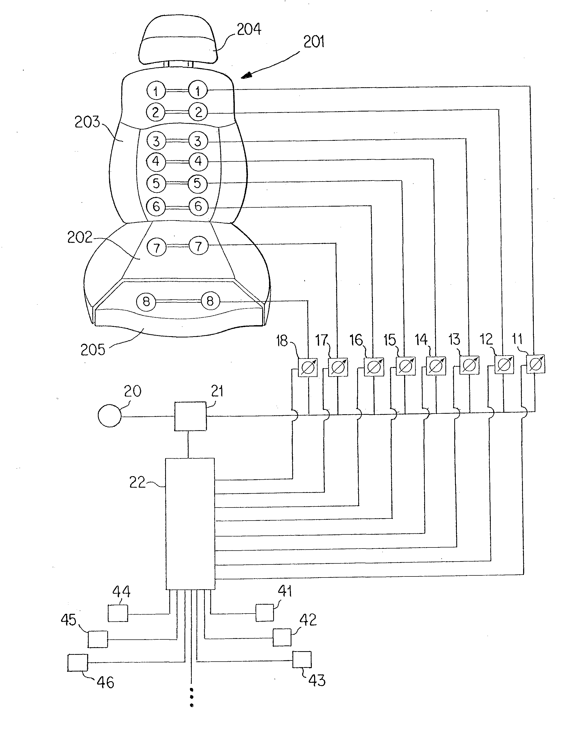
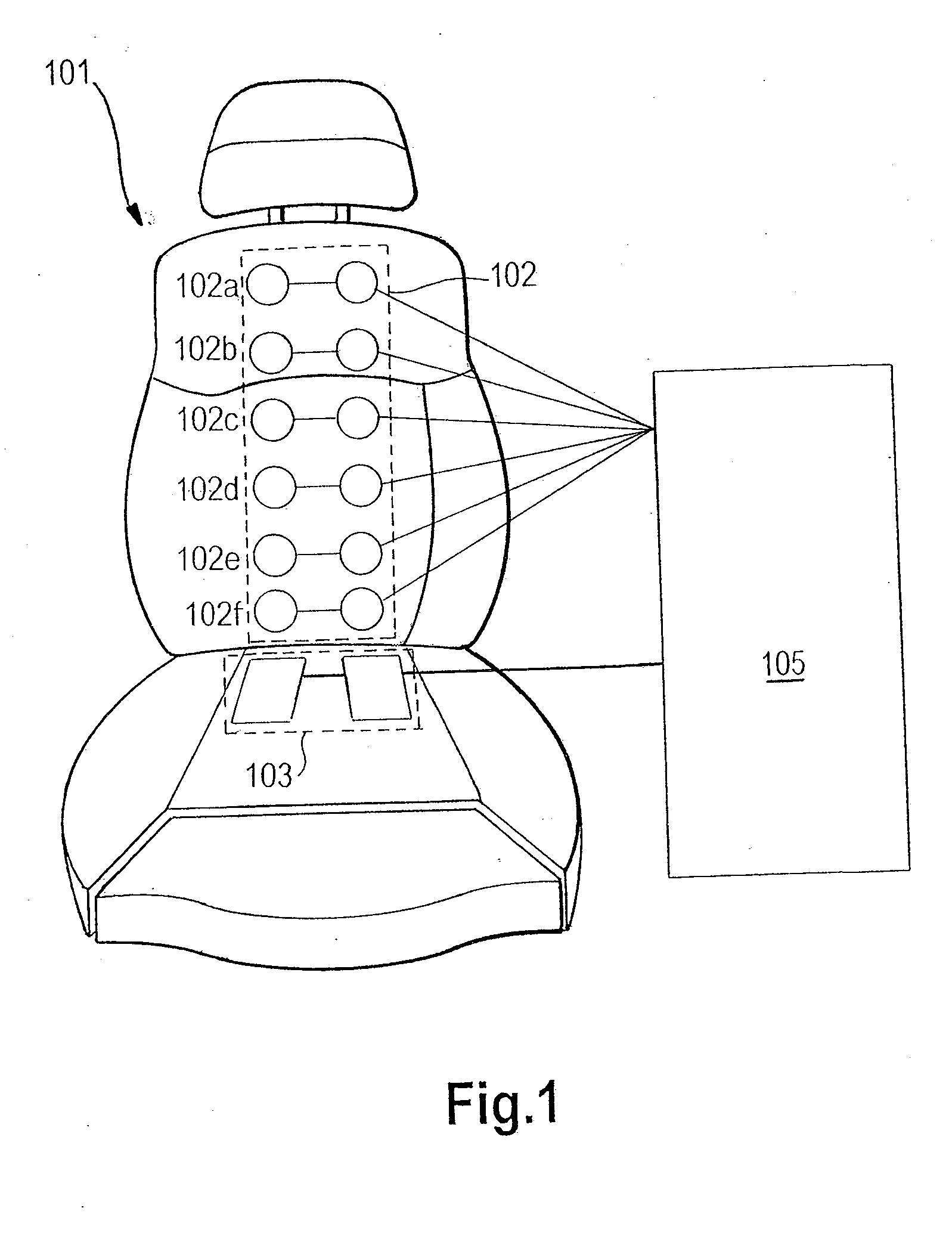
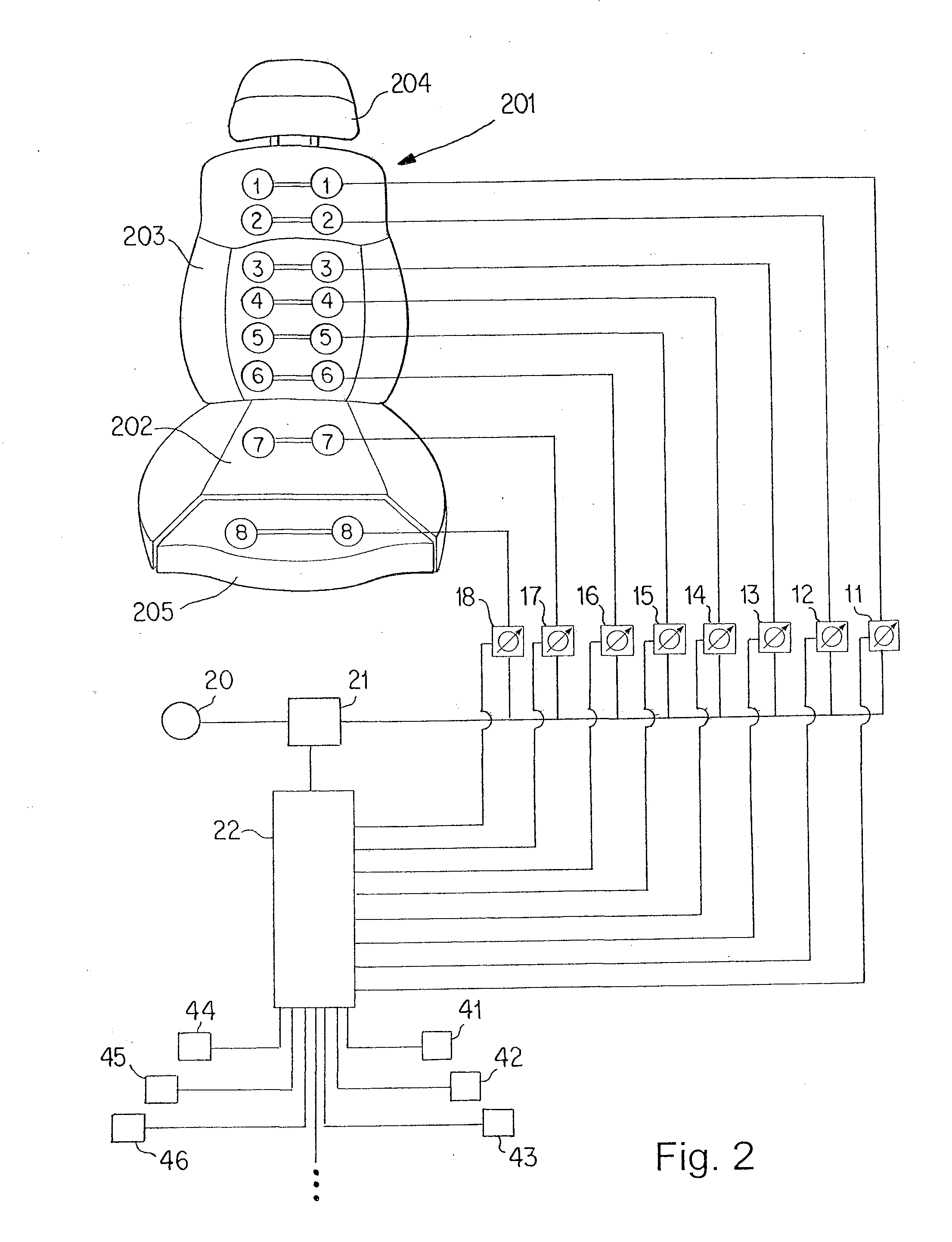
[0082]FIG. 2 shows a a seat according to a first embodiment of the invention. The seat 201 includes a seat cushion 202, a backrest 203, a headrest 204, and a thigh support 205 as part of the seat cushion 202. Six pairs of lifting elements 1 to 6 are disposed above one another in the backrest 203. Two pairs of lifting elements 7 and 8 are provided in the seat cushion 202. The lifting elements 1 to 6 are used for massaging purposes while the lifting elements 7 are used for the mobilization of the spinal column. In this respect, the structure of the seat 201 corresponds to the related art seat shown in FIG. 1. Furthermore, the lifting elements 8 are provided for massaging purposes in the thigh support.

[0083]A pneumatic pump 20 acts by way of a valve 21 on the pairs of lifting elements 1 to 8 with the interposition of pressure sensors 11 to 18. The pressure sensors 11 to 18 each additionally have a throttle function for regulating the pressure in the pairs of lifting elements 1 to 8.

[00...

Example

[0122]In a second embodiment of the invention shown in FIG. 3, the number of sensors is reduced. Two sensors 31 and 32 are provided here which are assigned to the lifting-element pairs 1, 2 and the lifting-element pairs 5, 6 respectively. The contact pressure applied by a user to the seat 201 is thus detected in two spatially separate regions of the backrest 203. By combining the two uppermost lifting-element pairs 1, 2 and the two lowermost lifting-element pairs 5, 6, an average pressure is determined in the upper and lower regions of the backrest 203. Similarly, sensors 33 and 34 are assigned to the lifting-element pairs 7, 8 in the seat cushion 202 respectively, as a result of which the pressure applied by a user to the rear and front regions of the seat cushion 202 can be detected.

[0123]Before a user sits down in the seat, a predetermined fill pressure (“primary pressure”) is applied to the lifting elements 1 to 8. When the user sits down in the seat, his back rests against the ...


PUM


Abstract

A method and a device for adjusting a seat are provided. The method includes the acts of detecting a pressure exerted by a user on the seat via a pneumatic sensor and/or a hydraulic sensor, and adjusting the seat based on the pressure exerted by the user. The device includes a pneumatic or hydraulic lifting element, a pneumatic or hydraulic pressure sensor connected to the lifting element, and a control unit connected to the pressure sensor. The pressure sensor detects a pressure exerted by a user on the seat, and the control unit controls the first lifting element to adjust the seat based on the pressure exerted by the user.

Description

CROSS-REFERENCE TO RELATED APPLICATIONS[0001]This application is a continuation of PCT International Application No. PCT / EP2008 / 009376, filed Nov. 6, 2008, which claims priority under 35 U.S.C. §119 from German Patent Application No. DE 10 2007 053 119.4, filed Nov. 8, 2007, the entire disclosures of which are herein expressly incorporated by reference.BACKGROUND AND SUMMARY OF THE INVENTION[0002]The invention relates to a method and a device for adjusting a seat.[0003]DE 10 2004 062 084 B3 relates to a device for automatically adapting a seat to the driver of a motor vehicle, the seat adjustment selected by the driver being detected and compared with stored target values. The actual detected values are adapted to the target values with the aid of components of the seat itself, by configuring these components to rest against the driver or by generating values of at least one person-specific parameter resulting from the action of the driver on the seat components. In doing so, a driv...

Claims


Application Information

Patent Timeline
IPC IPC(8): B60N2/44A47C7/00A47C7/46G06F19/00A47C7/14B60N2/66G01L1/02B60N2/90
CPCB60N2/4415B60N2/0244B60N2/914
Inventor ZENK, RAPHAELFRANZ, MATTHIASDURT, ALEXANDERLEIN, RUDOLF
Owner BAYERISCHE MOTOREN WERKE AG
Why Eureka
Try Eureka