Compact brush holder assembly having dynamic loading and improved brush box holder

Inactive Publication Date: 2010-11-04
CLEMENTE ROGER
View PDF4 Cites 0 Cited by
  • Summary
  • Abstract
  • Description
  • Claims
  • Application Information

AI Technical Summary

Benefits of technology

[0006]An object of the present invention is to provide for a novel brush box holder assembly in which the brush box has minimal contact with the brush thereby reducing friction and binding.
[0007]A further object of the present invention is to provide for a novel brush box holder assembly which could easily be stamped out of metal.

Problems solved by technology

Both designs limit brush movement, resist brush cooling, require complicated brush holder designs, and necessitate substantial space for installation.
Previously assemblies restrict how the constant-force spring is held in place because the spring manufacturers recommendations limit the approved method to return the constant-force spring to the outside portion of the coiled sections.

Method used


Image

  • Compact brush holder assembly having dynamic loading and improved brush box holder
  • Compact brush holder assembly having dynamic loading and improved brush box holder
  • Compact brush holder assembly having dynamic loading and improved brush box holder

Examples


Embodiment Construction

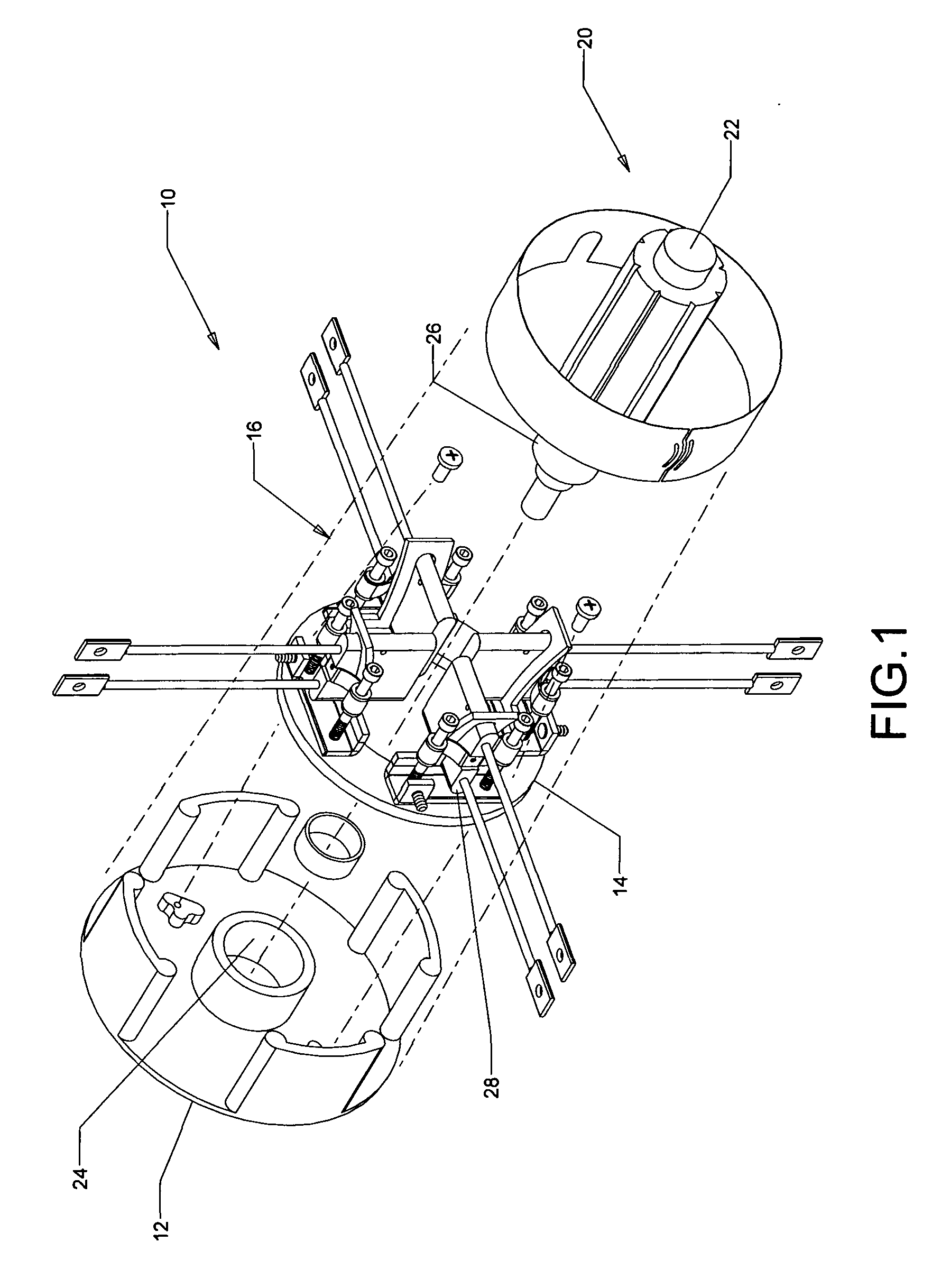
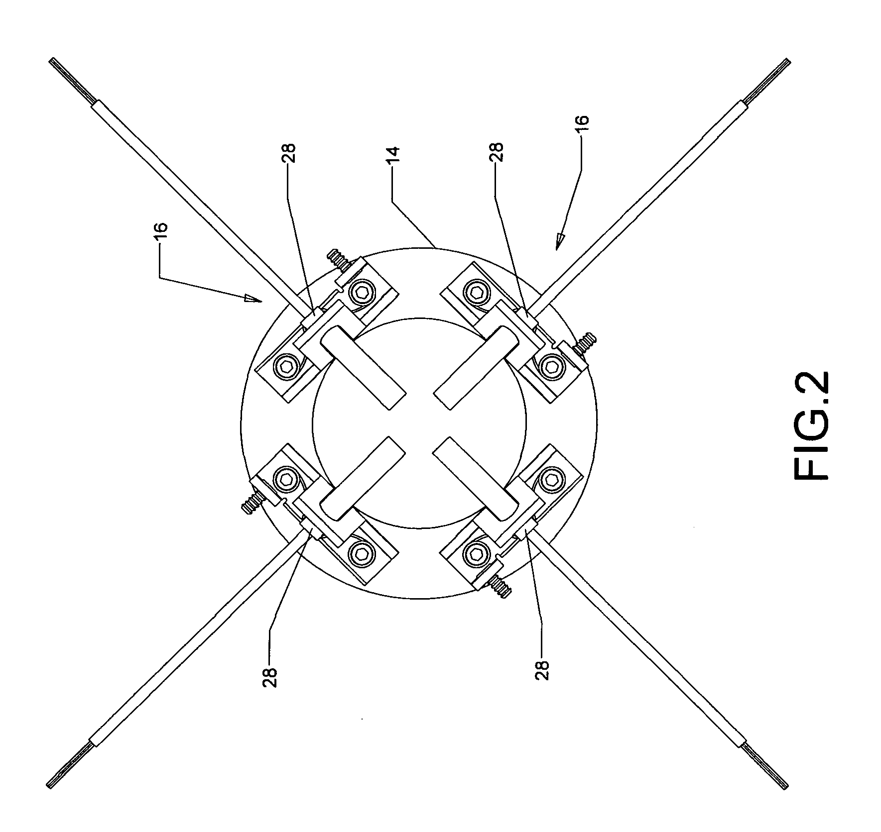
[0023]Referring now to the drawings, and particularly FIGS. 1 and 2, there is illustrated a dynamoelectric machine generally indicated as 10. The dynamoelectric machine 10 may be a conventional DC motor having a tubular frame (not shown) and a cover or end frame 12, attached to an open end of the tubular frame such as by bolts (not shown) in a conventional manner. An insulated support or yolk member 14 is provided with a plurality of brush and brush holder assemblies, generally indicated as 16, disposed equidistantly and radially on the yolk 14. The yolk 14 is fastened to the end frame 12 of the machine 10 in a manner known to one skilled in the art. The yolk 14 is preferably fabricated from a thermoplastic dielectric material and is formed with orifices to provide for the mounting of such brush holder assembly 16, as well as to provide mounting of the yolk 14 to the end frame 12 of the machine 10.

[0024]Interiorly of the tubular frame of the machine 10 there is provided an armature ...


PUM


Abstract

These and other objects of the present invention are achieved by a brush holder assembly for an electric motor or generator wherein the brush box or holder is arcuate and curved in relationship to a commutator and supports a brush means and a floating constant force spring which allows dynamic movement and control of the brush as it moves towards a commutator.

Description

RELATED APPLICATIONS[0001]Applicant claims the benefit of provisional application Ser. No. 61 / 215,097, filed May 4, 2009.BACKGROUND OF THE INVENTION[0002]1. Field of the Invention[0003]The invention relates to electric machines, and more particularly, to a brush holder assembly for an electric motor.[0004]2. Description of the Prior Art[0005]Brush holder assemblies which control the movement of the brush against the commutator having a critical affect on overall motor performance. There are numerous designs which are currently used by motor manufacturers including assemblies which use constant force springs to control brush movement against the commutator. Some assemblies limit brush loading to the front, while others can be loaded from the back. On the latter, the constant force spring must be removed to install a new brush. Both designs limit brush movement, resist brush cooling, require complicated brush holder designs, and necessitate substantial space for installation. Previous...

Claims


Application Information

Patent Timeline
IPC IPC(8): H01R39/40
CPCH01R39/40
Inventor CLEMENTE, ROGER
Owner CLEMENTE ROGER
Why Eureka
Try Eureka