Driving device

Inactive Publication Date: 2010-11-04
KONICA MINOLTA OPTO
View PDF19 Cites 2 Cited by
  • Summary
  • Abstract
  • Description
  • Claims
  • Application Information

AI Technical Summary

Benefits of technology

[0017]According to this configuration, lack of forces for the expansion and contraction in some of the expandable portions makes it possible to adjust a direction in which the forces for the expansion and contraction of the electromechanical transducer are balanced and to widen choices for the direction of inclination of the driving member.
[0018]According to the invention, the slide displacement of

Problems solved by technology

According to this configuration, expansion and contraction of the electromechanical transducer with a short period cause vibrations of the driving member and the slide displacement of the movable member in the di

Method used


Image

  • Driving device
  • Driving device
  • Driving device

Examples


first embodiment

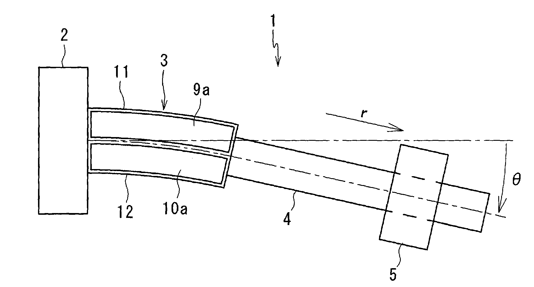
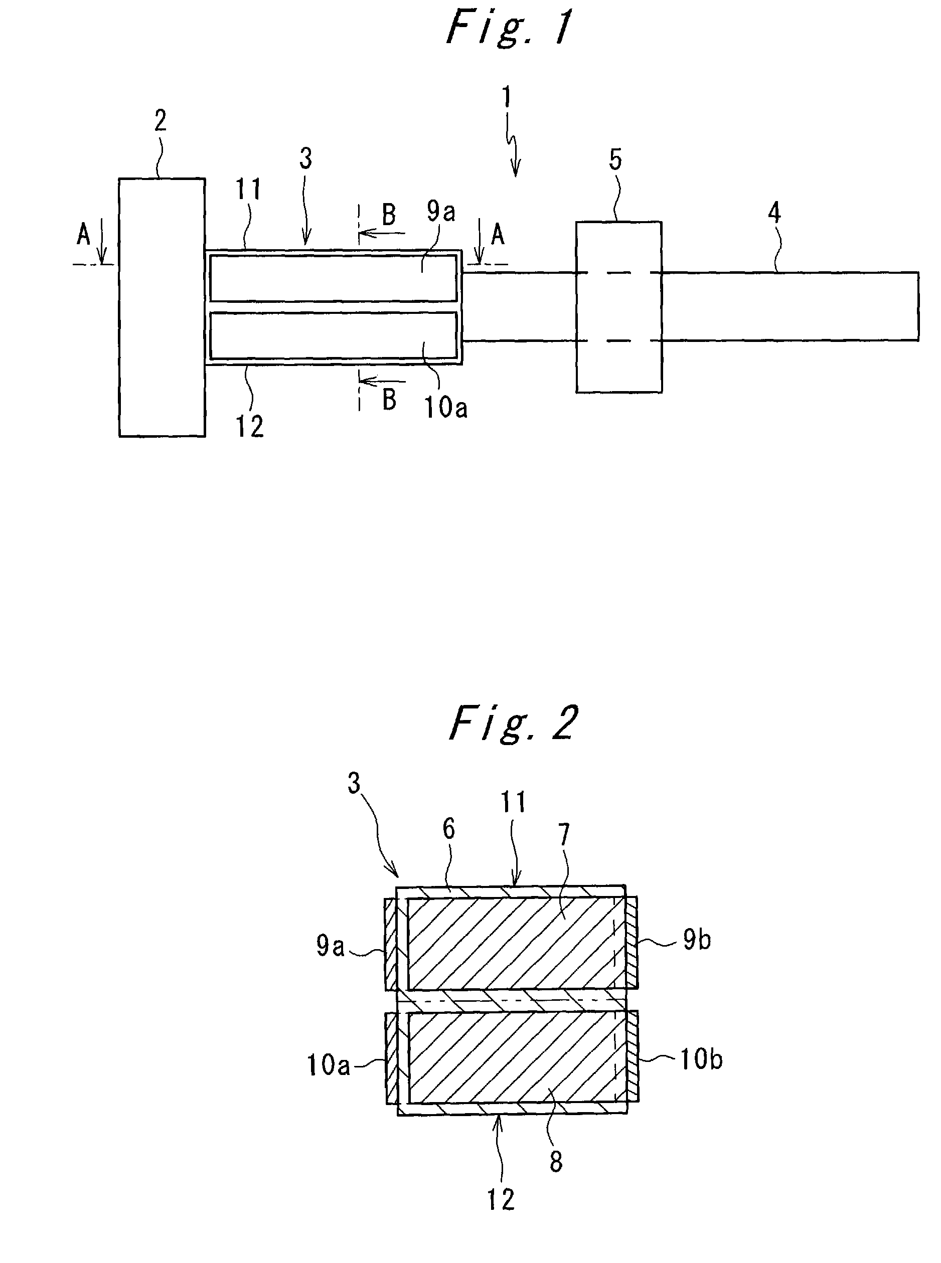
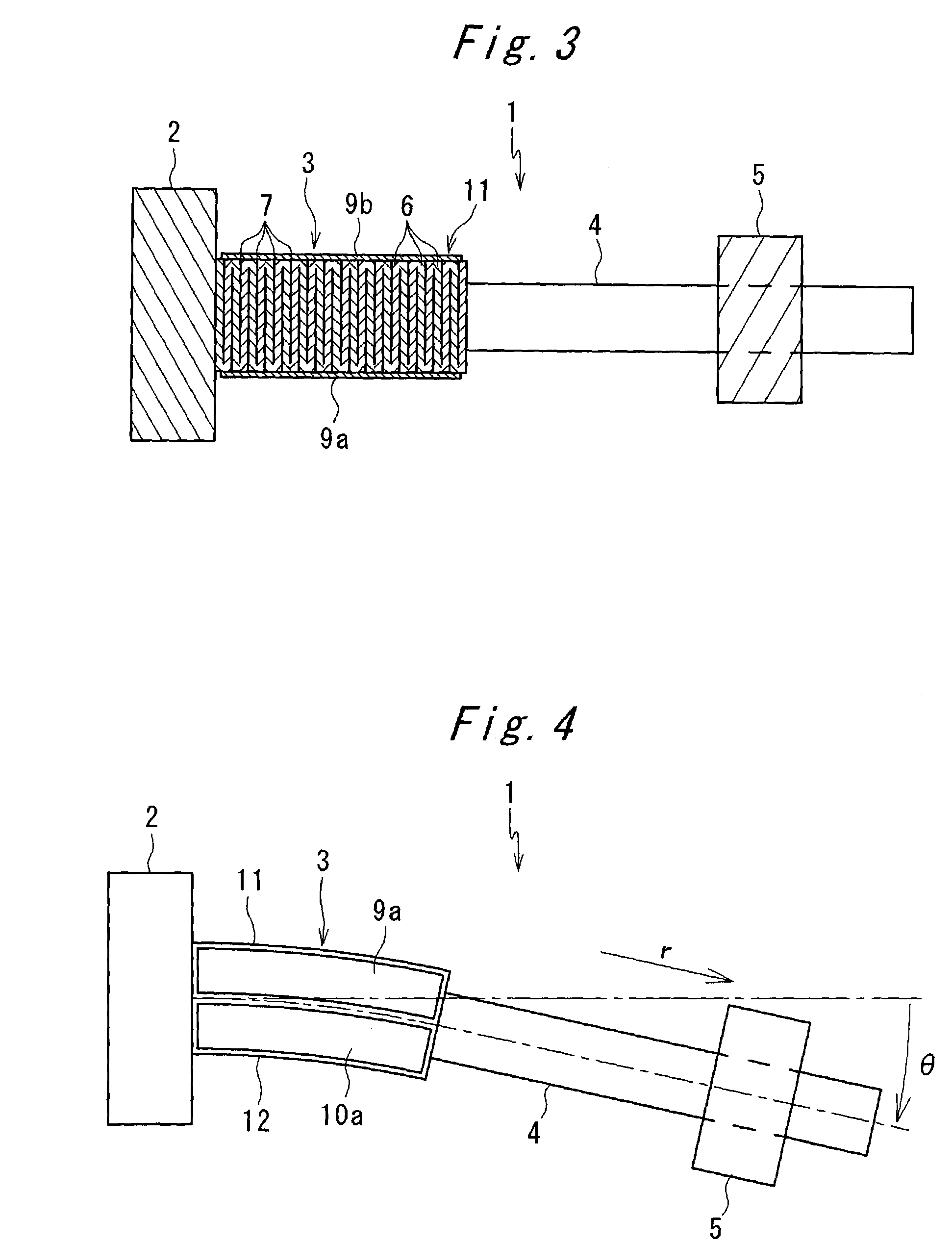
[0030]Hereinbelow, embodiments of the present invention will be described with reference to the drawings. FIGS. 1 through 3 show a driving device 1 of the present invention. The driving device 1 comprises of a weight 2, a piezoelectric element (electromechanical transducer) 3 having one end fixed to the weight 2, a shaft-like driving member 4 having one end fixed to the other end of the electromechanical transducer 3, and a movable member 5 which is engaged frictionally on the driving member 4 so as to be capable of slidingly displacing.

[0031]As shown in FIGS. 2 and 3, the piezoelectric element 3 is formed of a sheet-like piezoelectric layer 6 on which two print electrodes 7, 8 are printed and which is laminated in a axial direction of the driving member 4, and external electrodes 9a, 9b, 10a, 10b which alternately connects the print electrodes 7, 8. In the piezoelectric element 3, an expandable portion 11 in which the print electrodes 7 are interposed expands and contracts in accor...

third embodiment

[0048]FIG. 10 shows a piezoelectric element 51 of a driving device 1 in accordance with the present invention. In the present embodiment, the piezoelectric element 51 is shaped like a hexagonal cylinder and has trigonal-prism-like expandable portions 52, 53, 54, 55, 56, 57 obtained from division thereof into sixths around a center axis C. In the present embodiment, a pair of external electrodes of each of the expandable portions 52, 53, 54, 55, 56, 57 are provided side by side on the same outer surface of the piezoelectric element 51.

[0049]As in the present embodiment, increase in number of the expandable portions in parallel in the piezoelectric element allows finer selection of the direction of inclination of the driving member. In a method of selecting the direction of inclination, for instance, there may be selected an asymmetrical pattern of voltage application such as application of a positive voltage to the expandable portions 52, 53, a negative voltage to the expandable port...


PUM


Abstract

A driving device capable of multidimensional positioning by the single device has a shaft-like driving member 4, an electromechanical transducer 3 which has a plurality of expandable portions 11, 12 and which holds one end of the driving member 4, the expandable portions being provided in parallel so that each of the expandable portions can separately expands and contracts in a axial direction of the driving member 4, and a movable member 5 which frictionally engages on the driving member 4 and which can displace slidingly on the driving member 4, and a drive circuit which applies to some of the expandable portions 11, 12 a low change rate of direct-current voltage component different from that applied to other expandable portions 11, 12, and which applies to all the expandable portions 11, 12 a common alternating voltage component fluctuating with a common period.

Description

[0001]This application is based on application No. 2009-110945 filed in Japan, the contents of which are hereby incorporated by reference.TECHNICAL FIELD[0002]The present invention relates to a driving device.BACKGROUND ART[0003]As disclosed in JP 2000-78861 A, there are publicly known driving devices of vibration type which cause asymmetrical vibrations of a driving member and slide displacement of a movable member engaged frictionally with the driving member.[0004]As disclosed in JP 2008-178209 A, JP 2008-172885 A and JP 2007-325466 A, there are also known driving devices (truss actuators) which frictionally drive a movable member held movably by guides or the like, using contact members which make elliptical motions through agency of a plurality of piezoelectric elements.[0005]In JP 2000-78861 A, JP 2008-178209 A, JP 2008-172885 A and JP 2007-325466 A are disclosed techniques for achieving a two-dimensional motion using a rotary motion through agency of a piezoelectric element in...

Claims


Application Information

Patent Timeline
IPC IPC(8): H02N2/04
CPCH01L41/0966H02N2/025H02N2/0095H10N30/2046
Inventor SHIBATANI, KAZUHIROTAKANO, MANJI
Owner KONICA MINOLTA OPTO
Why Eureka
Try Eureka