
Optical fiber connector adapter

Inactive Publication Date: 2010-11-04
ADVANCED CONNECTEK INC
View PDF4 Cites 7 Cited by
  • Summary
  • Abstract
  • Description
  • Claims
  • Application Information

AI Technical Summary

Benefits of technology

[0012]The main objective of the invention is to provide an optical fiber connector adapter that facilitates reworking thereof, prevents an expensive and time-wasting ultrasound welding process when assembled therefore to improve the fabrication and production rate of the optical fiber connector adapter.
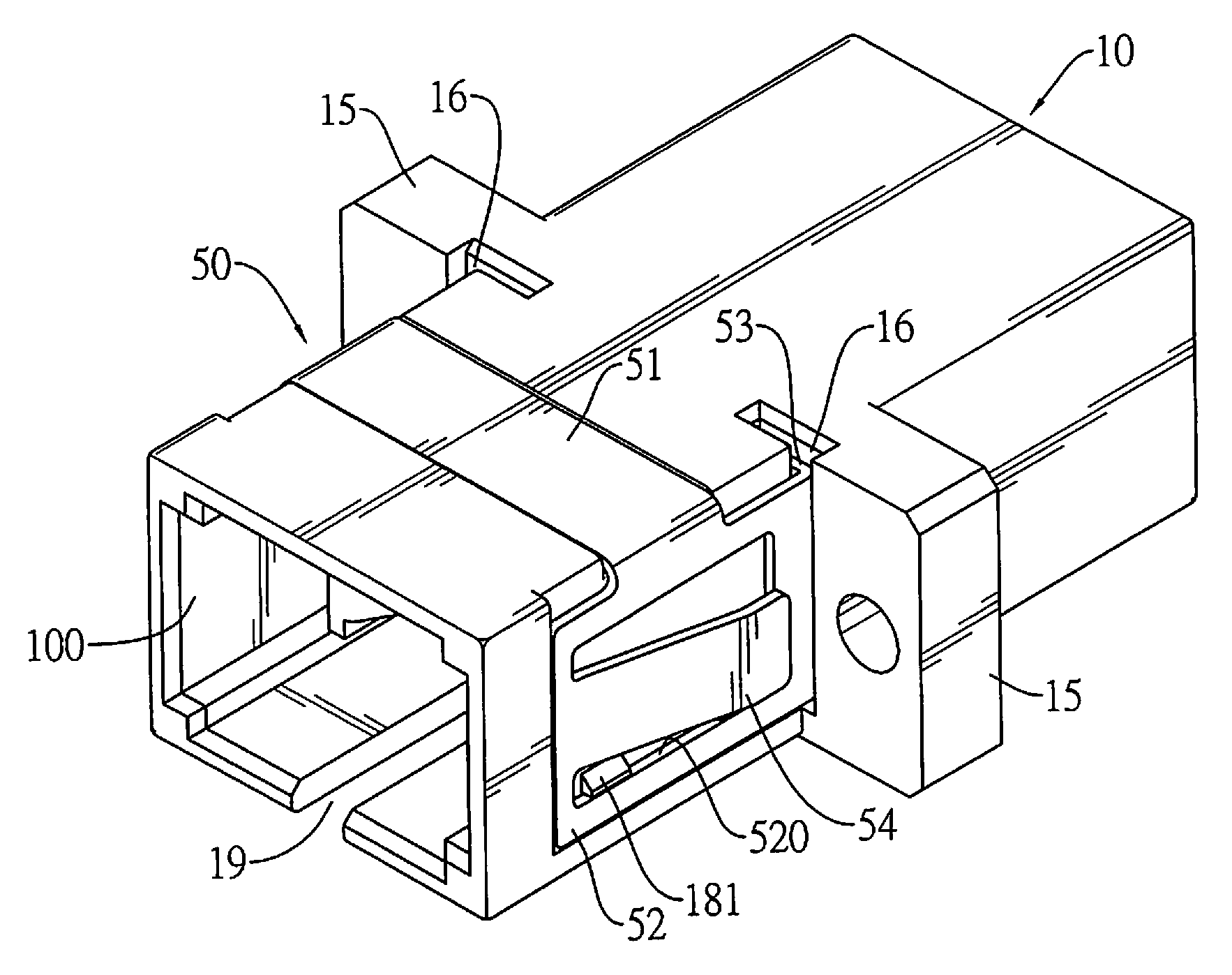
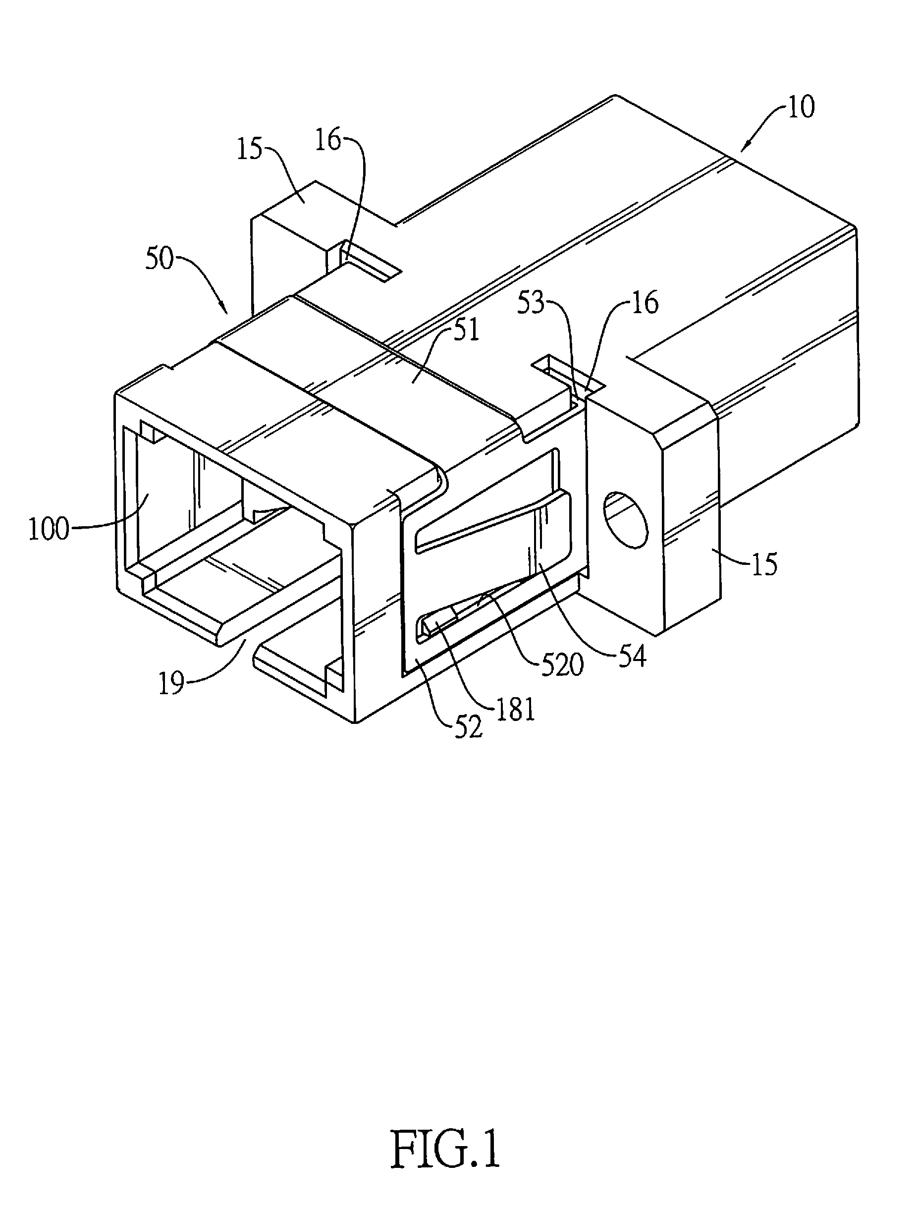
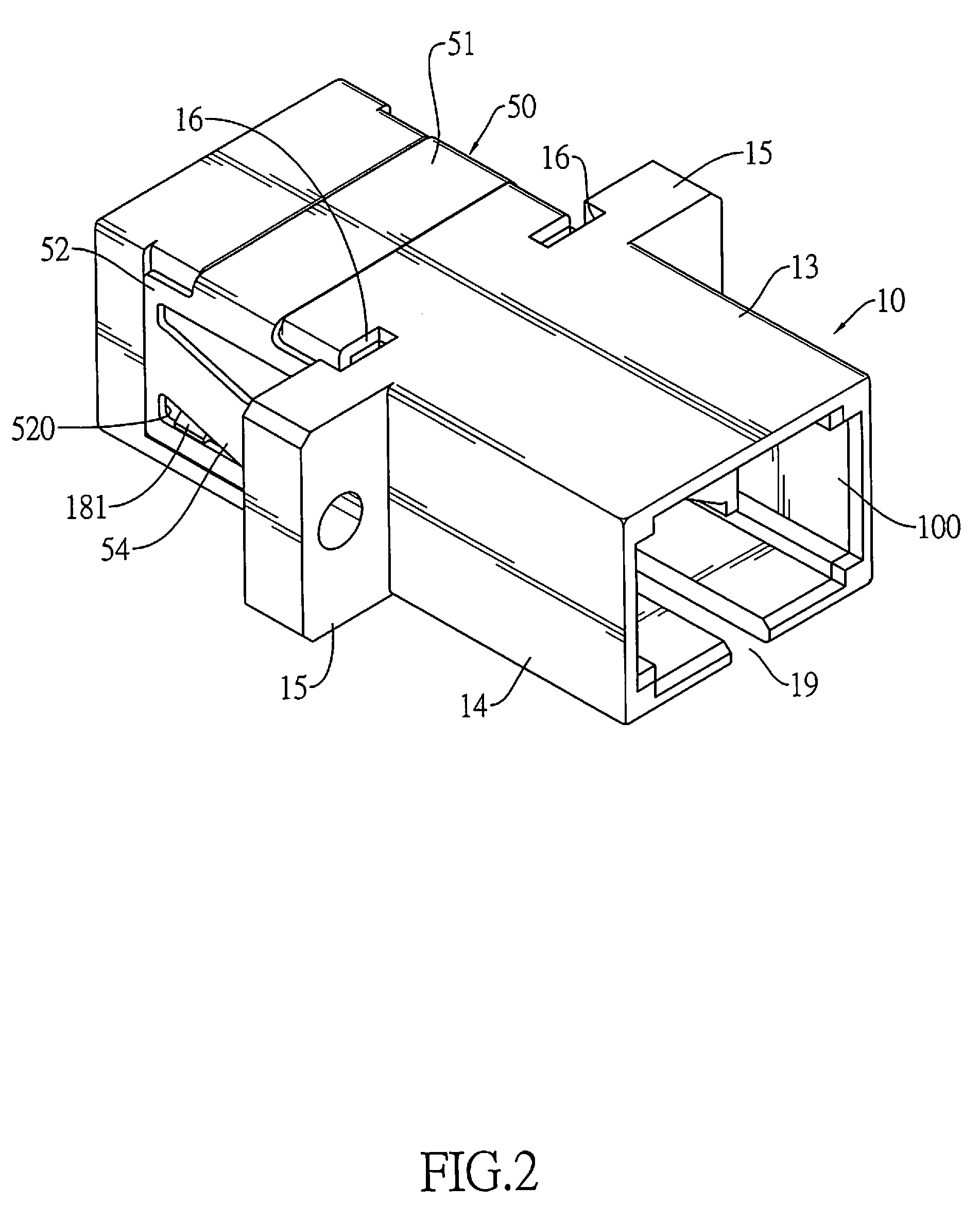
[0013]An optical fiber connector adapter has a housing, a front sleeve holder, a rear sleeve holder, a sleeve and detachable positioning member. The housing has a cavity, two limiting protrusions and two positioning slots. The cavity and positioning slots are defined in the housing. The limiting protrusions are formed in the cavity. The front and sleeve holders are mounted in the cavity and each has a tube and a mount abutting the limiting protrusions. The sleeve is mounted in the tubes. The detachable positioning member is mounted on the housing and has two stoppers extending respectively the positioning slots to make the mounts clamped between the limiting protrusions and the stoppers. The optical fiber connector adapter with the detachable positioning member may be detached easily to facilitate rework.

Problems solved by technology

1. The housing having the flange and second cylinder in the cavity is structurally complicated so that manufacturing the housing by insert molding processes is difficult. Therefore, the optical connector adapter has an undesirable low production rate and a high manufacturing cost.
2. The U-shaped engagement pin is thin and tiny therefore requires precisely and carefully manual or automated alignment so that fabricating the engagement pin is difficult and wastes times. Furthermore, the engagement pin fully inserted in the insertion groove can not be drawn out without specific hand tools. When the sleeve breaks during fabrication or operation of the optical connector adapter, a fabricator or user can not easily dissemble the optical connector adapter to rework. Forcing to dissemble the optical connector adapter damages the housing.
However, the ultrasound welding process requires external power so wastes energy and time and has a high cost.
Furthermore, the welded front and rear housings can not be disassembled so that reworking the optical connector adapter is impossible.
Moreover, the welded front and rear housings have uneven outer surfaces and deckle edges so that the appearance of the optical connector adapter is undesirable.

Method used


Image

  • Optical fiber connector adapter
  • Optical fiber connector adapter
  • Optical fiber connector adapter

Examples


Embodiment Construction

[0023]With reference to FIGS. 1 to 4, an optical fiber connector adapter in accordance with the present invention may accommodate two optical fiber plug connectors and may be compatible with the subscriber connectors (SC) standard to accommodate and hold two SCs.

[0024]The optical fiber connector adapter comprises a housing (10), a front sleeve holder (20), a rear sleeve holder (20a), a sleeve (30) and a detachable positioning member (50).

[0025]With further reference to FIGS. 5 to 7, the housing (10) has a front (11), a rear (12), a top (13), a bottom, two opposite sides (14), a cavity (100), two limiting protrusions (151) and two positioning slots (16) and may further have a top indentation (17), two opposite side indentations (18), two opposite protruding blocks (15) and two alignment slits (19).

[0026]The cavity (100) is defined in the housing (10) through the front (11) and the rear (12) and has an inner surface.

[0027]The limiting protrusions (151) are formed on and protrude trans...


PUM


Abstract

An optical fiber connector adapter has a housing, a front sleeve holder, a rear sleeve holder, a sleeve and detachable positioning member. The housing has a cavity, two limiting protrusions and two positioning slots. The cavity and positioning slots are defined in the housing. The limiting protrusions are formed in the cavity. The front and sleeve holders are mounted in the cavity and each has a tube and a mount abutting the limiting protrusions. The sleeve is mounted in the tubes. The detachable positioning member is mounted on the housing and has two stoppers extending respectively the positioning slots to make the mounts clamped between the limiting protrusions and the stoppers. The optical fiber connector adapter with the detachable positioning member may be detached easily to facilitate rework.

Description

BACKGROUND OF THE TON[0001]1. Field of the Invention[0002]The present invention relates to an adapter, and more particularly to an optical fiber connector adapter that facilitates reworking thereof, prevents an expensive and time-wasting ultrasound welding process when assembled therefore to improve the fabrication and production rate of the optical fiber connector adapter.[0003]2. Description of Related Art[0004]Optical connector adapters are used to connecting two optical cables together therefore to extend a total length of the optical cables to facilitate arrangements of optical devices.[0005]U.S. Pat. No. 6,431,762 discloses an optical connector adapter having a sleeve holder, a housing, a sleeve and an engagement pin.[0006]The sleeve holder has a first cylinder, claws and a flange. The housing is hollow and has a cavity, an insertion groove, a flange and a second cylinder. The cavity accommodates and holds the sleeve holder. The insertion groove is defined in the housing. The ...

Claims


Application Information

Patent Timeline
IPC IPC(8): G02B6/00
CPCG02B6/3825
Inventor HSU, MIN-CHAOWU, CHUN-HSIUNGTUNG, SHANG-YI
Owner ADVANCED CONNECTEK INC
Learn More