Polarized glasses type stereoscopic image display device and fabrication method thereof

a stereoscopic image and display device technology, applied in the field of polarized glasses type stereoscopic image display device and a fabrication method thereof, can solve the problem of reducing the aperture ratio in proportion to the increase in the width of the black matrix, and achieve the effects of enhancing the vertical viewing angle and aperture ratio, preventing scratches, and enhancing the quality of 3d images

Inactive Publication Date: 2013-06-06
LG DISPLAY CO LTD
View PDF4 Cites 13 Cited by
  • Summary
  • Abstract
  • Description
  • Claims
  • Application Information

AI Technical Summary

Benefits of technology

[0021]An object of the present invention is to provide a polarized glasses type stereoscopic image display device and a fabrication method thereof in which a light blocking pattern is formed on a rear surface of the color filter substrate, thereby enhancing vertical viewing angle and aperture ratio.
[0022]Another object of the present invention is to provide a polarized glasses type stereoscopic image display device and a fabrication method thereof in which a light blocking pattern is formed of a metal having a large hardness, as well as a step height from the rear surface ITO is removed, thereby preventing a scratch due to an abrasive belt.
[0024]In order to accomplish the foregoing object, there is provided a polarized glasses type stereoscopic image display device, and the device may include a display panel in which a color filter substrate and an array substrate are bonded together to display the left and right eye images on pixels for each line; a plurality of light blocking pattern made of a metal having a value of 5 to 10 based on Mohs hardness, and formed in a stripe shape on a rear surface of the color filter substrate between vertically adjacent pixels; a electrostatic discharging layer covering the plurality of light blocking pattern and reducing a step height of the plurality of light blocking pattern; a polarizing plate adhered on the plurality of electrostatic discharging pattern; and a patterned retarder adhered on the polarizing plate to spatially divide the left and right eye images displayed through the display panel.
[0030]Furthermore, a method of fabricating a polarized glasses type stereoscopic image display device according to an embodiment of the present invention may include forming a plurality of light blocking pattern in a stripe shape on a rear surface of the color filter substrate on which a color filter layer is formed; forming a electrostatic discharging layer covering the plurality of light blocking pattern and reducing a step height of the plurality of light blocking pattern; bonding the color filter substrate formed with the plurality of light blocking pattern to an array substrate to form a display panel for displaying the left and right eye images on pixels for each line; adhering a polarizing plate on the electrostatic discharging layer of the color filter substrate in the display panel; and adhering a patterned retarder for spatially dividing the left and right eye images displayed through the display panel on the polarizing plate.
[0039]As described above, according to a polarized glasses type stereoscopic image display device and a fabrication method thereof in accordance with the present invention, a light blocking pattern may be formed on a rear surface of the color filter substrate, thereby enhancing vertical viewing angle and aperture ratio. As a result, it may provide an effect of enhancing the quality of 3D images in the stereoscopic image display device.
[0040]Furthermore, according to a polarized glasses type stereoscopic image display device and a fabrication method thereof in accordance with the present invention, a light blocking pattern is formed of a metal having a large hardness instead of resin BM, as well as a step height from the light blocking pattern is reduced, thereby preventing a scratch due to an abrasive belt. As a result, it may be possible to enhance process yield as well as facilitate the rework of a polarizing plate since the light blocking pattern is formed of a metal, thereby providing an effect of reducing fabrication cost.

Problems solved by technology

Due to this, in the related art, it has been enhanced by increasing a width of the black matrix 6 on the upper glass substrate 5, but in this case, a problem of reducing an aperture ratio in proportion to the increased width of the black matrix 6 is created.

Method used


Image

  • Polarized glasses type stereoscopic image display device and fabrication method thereof
  • Polarized glasses type stereoscopic image display device and fabrication method thereof
  • Polarized glasses type stereoscopic image display device and fabrication method thereof

Examples


first embodiment

[0055]FIG. 3 is an exemplary view schematically illustrating the structure of a polarized glasses type stereoscopic image display device according to the present invention.

[0056]FIG. 4 is a cross-sectional view schematically illustrating the structure of a polarized glasses type stereoscopic image display device according to a first embodiment of the present invention, in which the process of viewing a stereoscopic image in the right eye lens of stereoscopic viewing glasses is illustrated as an example.

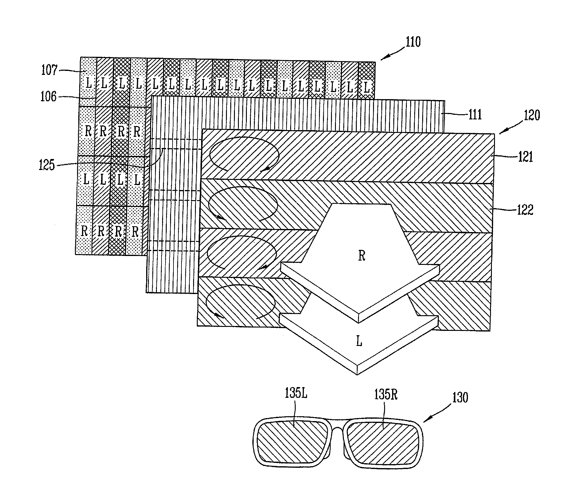
[0057]Referring to FIGS. 3 and 4, the polarized glasses type is a scheme of using a polarization phenomenon in which a patterned retarder 120 is disposed on a front surface of the display panel 110 to spatially divide the left and right eye images.

[0058]The patterned retarder 120 of the polarized glasses type stereoscopic image display device may be characterized in that a predetermined pattern is formed based on the location, thereby allowing the L, R images (L, R) to implement a pol...

second embodiment

[0077]Therefore, the light blocking patterns with a metal are applied to the

[0078]The hardness scale of metal used for the light blocking pattern is higher than that of the abrasive 141, thereby enduring the polishing of abrasive belt. And it can be stepped down of light blocking pattern because the metal having high hardness scale is used for the light blocking pattern.

[0079]And the electrostatic discharging layer is deposited on the entire surface of the light blocking pattern to stepped down of the light blocking pattern and discharging the electrostatic generated in the process of cutting or scribing. The electrostatic discharging layer is made of transparent conductive electrode such as ITO or IZO. As a result, a scratch due to an abrasive belt may be prevented by forming a light blocking pattern with a metal having a large hardness instead of resin BM and reducing a step height with the light blocking pattern, and it will be described in detail through the following second and...

third embodiment

[0105]FIG. 9 is a cross-sectional view schematically illustrating a polarized glasses type stereoscopic image display device according to the present invention, and a case where a light blocking pattern is formed of a metal having a large hardness and then a electrostatic discharging patterns, that is rear surface ITO patterns are formed between the light blocking patterns using a lift-off method is illustrated as an example. And the rear surface ITO patterns are connected each other electrically to discharge the electrostatic generated in the process of cutting or scribing.

[0106]Furthermore, FIG. 10 is a plan view schematically illustrating a rear surface of the upper glass substrate in a polarized glasses type stereoscopic image display device according to a third embodiment of the present invention illustrated in FIG. 9.

[0107]Referring to FIGS. 9 and 10, as described above, the polarized glasses type is a scheme of using a polarization phenomenon in which a patterned retarder 320...


PUM

PropertyMeasurementUnit
depthaaaaaaaaaa
thicknessaaaaaaaaaa
heightaaaaaaaaaa

Abstract

According to a polarized glasses type stereoscopic image display device and a fabrication method thereof in accordance with the present invention, a light blocking pattern may be formed on a rear surface of the color filter substrate to enhance vertical viewing angle and aperture ratio. Moreover a light blocking pattern may be formed of a metal having a large hardness instead of resin BM and a step height from the rear surface ITO may be removed to prevent a scratch due to an abrasive belt.

Description

CROSS-REFERENCE TO RELATED APPLICATIONS[0001]This application claims the benefit of Korean Patent Application No. 10-2011-0128538, filed on Dec. 2, 2011, which is hereby incorporated by reference for all purposes as if fully set forth herein.BACKGROUND OF THE INVENTION[0002]1. Field of the Invention[0003]The present invention relates to a polarized glasses type stereoscopic image display device and a fabrication method thereof, and more particularly, to a polarized glasses type stereoscopic image display device and a fabrication method thereof capable of viewing a stereoscopic image using polarized glasses.[0004]2. Description of the Related Art[0005]Three-dimensional (3D) display may be briefly defined as “all types of systems for artificially generating a 3D screen.”[0006]Here, a system may include software technologies that can be seen as three-dimensional images and hardware for actually implementing contents made by the software technologies. As described above, the system incl...

Claims


Application Information

Patent Timeline
Patent Type & Authority Applications(United States)
IPC IPC(8): H04N13/04H04N13/30G02B30/25
CPCG02F1/133512G02F2201/40G02F2201/503Y10T156/10H04N13/0434H04N2213/008G02B27/26H04N13/04G02B30/25G02B30/27H04N13/30H04N13/337G02B30/00
Inventor KWON, DHANG
Owner LG DISPLAY CO LTD
Why Eureka
Try Eureka