Tooth movement system and method

a technology of tooth movement and tooth structure, applied in the field of dental care, can solve the problems of insufficient pre-determined treatment time, arch wires may need to be changed, brackets may need repositioning,

Active Publication Date: 2010-11-04
DENTSPLY IMPLANTS NV
View PDF16 Cites 156 Cited by
  • Summary
  • Abstract
  • Description
  • Claims
  • Application Information

AI Technical Summary

Benefits of technology

[0009]The present invention has an object to analyze a patient's dentition and to determine an orthodontic treatment plan by simulating an intervention in advance. The current invention describes the use of 3D imaging techniques and computer technology to simulate and predict tooth movement as a function of the chosen treatment, i.e. a specific orthodontic appliance. In this way treatment options can be compared and the most optimal (shortest treatment time, lowest forces . . . ) treatment for each individual patient can be selected.
[0010]The current invention differs from above-mentioned prior art in the sense that the sub-steps of the tooth movement are not predefined but computed based on a simulation of brackets and wire as they would be used in the orthodontic treatment of the patient. This means that the sub-steps are calculated based on the relationship between the applied loads and the tooth movement; only one of both parameters can be chosen freely. Thus, either the tooth load is specified and applied in order to calculate the resulting tooth movement or vice versa the tooth movement is specified and applied in order to calculate the tooth load that should be applied. Moreover, the current invention allows predicting the time at which brackets and / or archwire should be changed, and comparing different treatment options with respect to tooth loading and duration.

Problems solved by technology

This means that brackets may need repositioning, arch wires may need to be changed.
The total treatment typically lasts one and a half up to two years, but the final treatment time is not well predictable in advance.

Method used

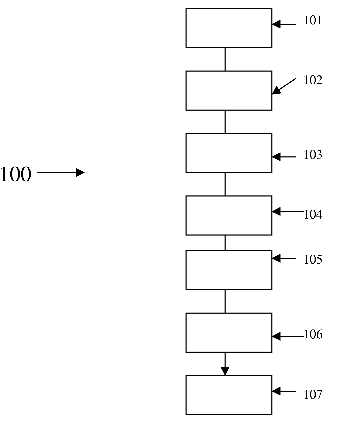
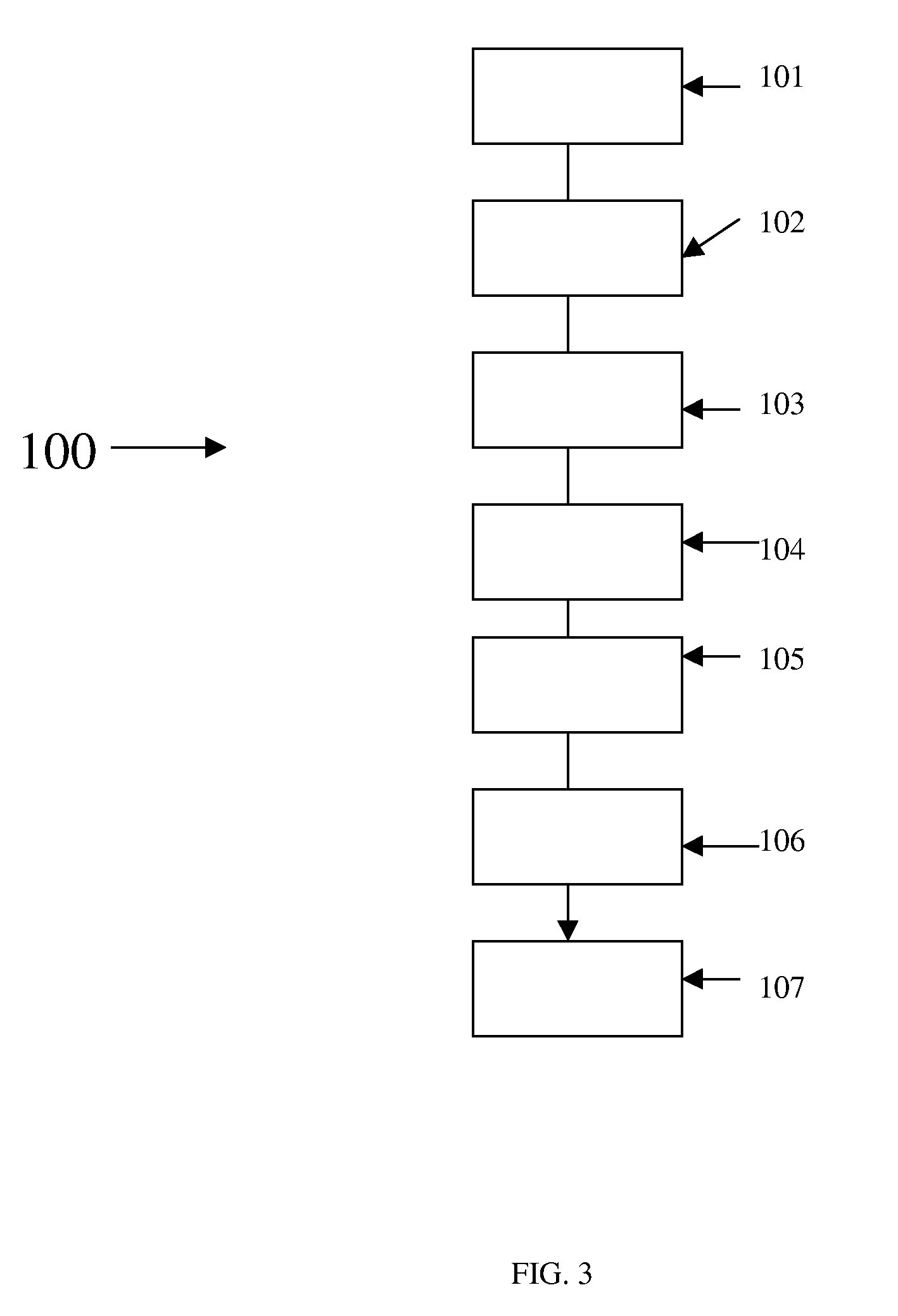

Image

  • Tooth movement system and method
  • Tooth movement system and method
  • Tooth movement system and method

Examples


Embodiment Construction

[0017]The present invention will be described with respect to particular embodiments and with reference to certain drawings but the invention is not limited thereto but only by the claims. The drawings described are only schematic and are non-limiting. In the drawings, the size of some of the elements may be exaggerated and not drawn on scale for illustrative purposes. The dimensions and the relative dimensions do not correspond to actual reductions to practice of the invention.

[0018]Furthermore, the terms first, second, third and the like in the description and in the claims, are used for distinguishing between similar elements and not necessarily for describing a sequence, either temporally, spatially, in ranking or in any other manner. It is to be understood that the terms so used are interchangeable under appropriate circumstances and that the embodiments of the invention described herein are capable of operation in other sequences than described or illustrated herein.

[0019]More...


PUM


Abstract

A patient's dentition is analysed to determine an orthodontic treatment plan by simulating an intervention in advance. 3D imaging techniques and computer technology are used to simulate and predict tooth movement as a function of the chosen treatment, i.e. a specific orthodontic appliance. In this way treatment options can be compared and the most optimal (shortest treatment time, lowest forces . . . ) treatment for each individual patient can be selected. Sub-steps of the tooth movement are not predefined but computed based on a simulation of orthodontic elements and wire as they would be used in the orthodontic treatment of the patient. This means that the sub-steps are calculated based on the relationship between the applied loads and the tooth movement; only one of both parameters can be chosen freely. Thus, either the tooth load is specified and applied in order to calculate the resulting tooth movement or vice versa the tooth movement is specified and applied in order to calculate the tooth load that should be applied. Moreover, the current invention allows predicting the time at which brackets and / or archwire should be changed, and comparing different treatment options with respect to tooth loading and duration.

Description

FIELD OF THE INVENTION[0001]The invention is related to the field of dentistry, more particular orthodontics. Three-dimensional digital imaging technology (CT, μCT, optical scanning . . . ) is ever more frequently used by the dentist to analyze the patient's dentition and to determine the orthodontic treatment plan and simulate the intervention in advance. The current invention describes the use of 3D imaging techniques and computer technology to simulate and predict tooth movement as a function of the chosen treatment, i.e. a specific orthodontic appliance. In this way treatment options can be compared and the most optimal (shortest treatment time, lowest forces . . . ) treatment for each individual patient can be selected.BACKGROUND TO THE INVENTION[0002]Orthodontic treatment is characterized by applying forces to individual teeth aimed at moving them to a desired position. To induce tooth movement efficiently, the forces applied on the teeth should be within a certain range: too ...

Claims


Application Information

Patent Timeline
Patent Type & Authority Applications(United States)
IPC IPC(8): G06F17/50
CPCA61C7/002A61C7/14A61C7/12
Inventor PATTIJN, VEERLEVAN ROIE, BERTVAN LIERDE, CARL
Owner DENTSPLY IMPLANTS NV
Why Eureka
Try Eureka