Simultaneous displacement device for sliding doors

Active Publication Date: 2010-11-11
KLEIN IBERICA
View PDF19 Cites 4 Cited by
  • Summary
  • Abstract
  • Description
  • Claims
  • Application Information

AI Technical Summary

Benefits of technology

[0024]Preferably, in order to take advantage of the maximum performance of the present invention, the synchronism of the third cogged belt and of the first cogged belt, both in the second and in t

Problems solved by technology

The simultaneous displacement device described above has important limitations and inconveniences.
The main limitation is that it only allows the simultaneous sliding of two sliding leaves running in the same direction and sense.
That is, it does not work with sliding doors the leaves of which run in a synchronized manner in opposite senses.
This limitation makes

Method used


Image

  • Simultaneous displacement device for sliding doors
  • Simultaneous displacement device for sliding doors
  • Simultaneous displacement device for sliding doors

Examples


Embodiment Construction

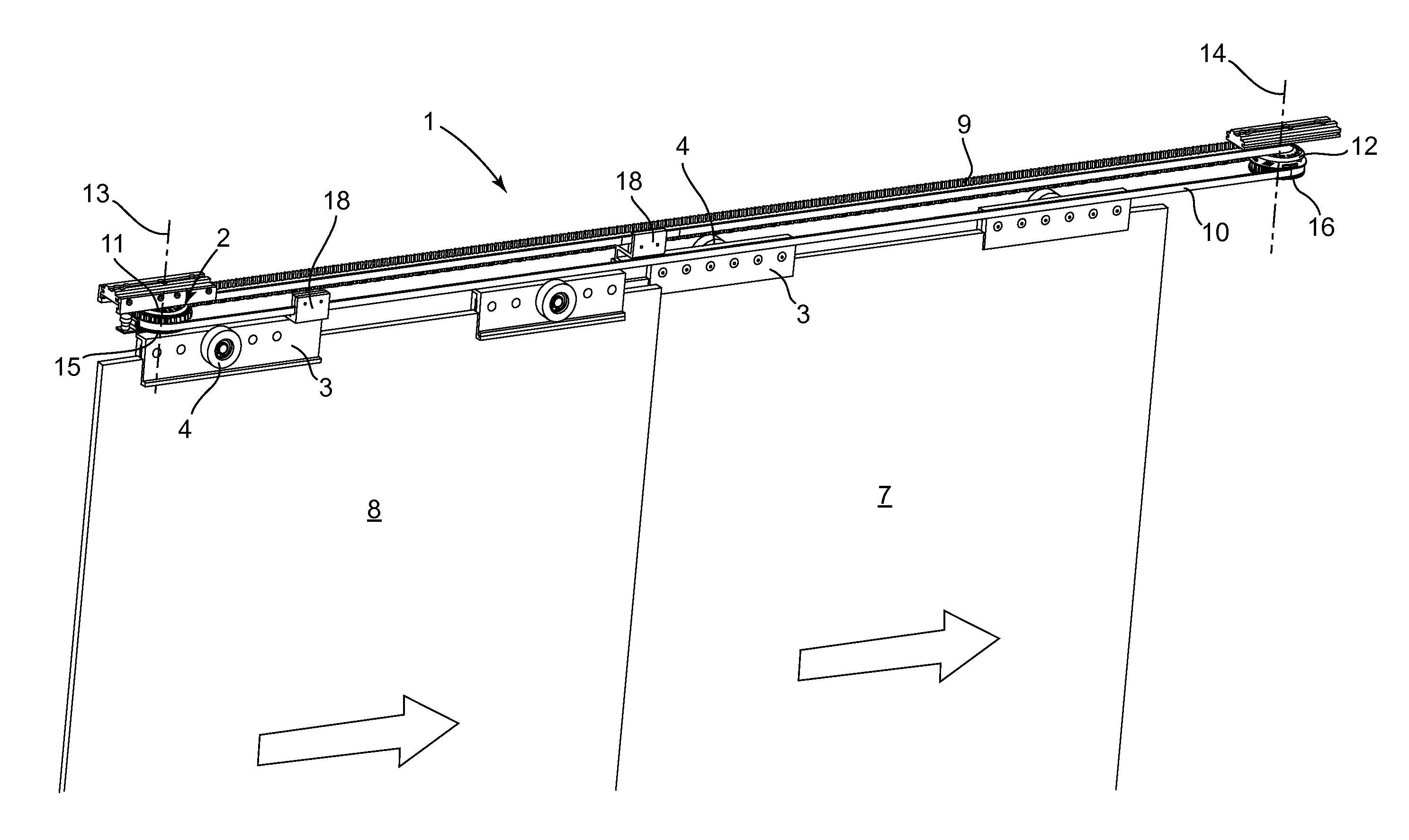
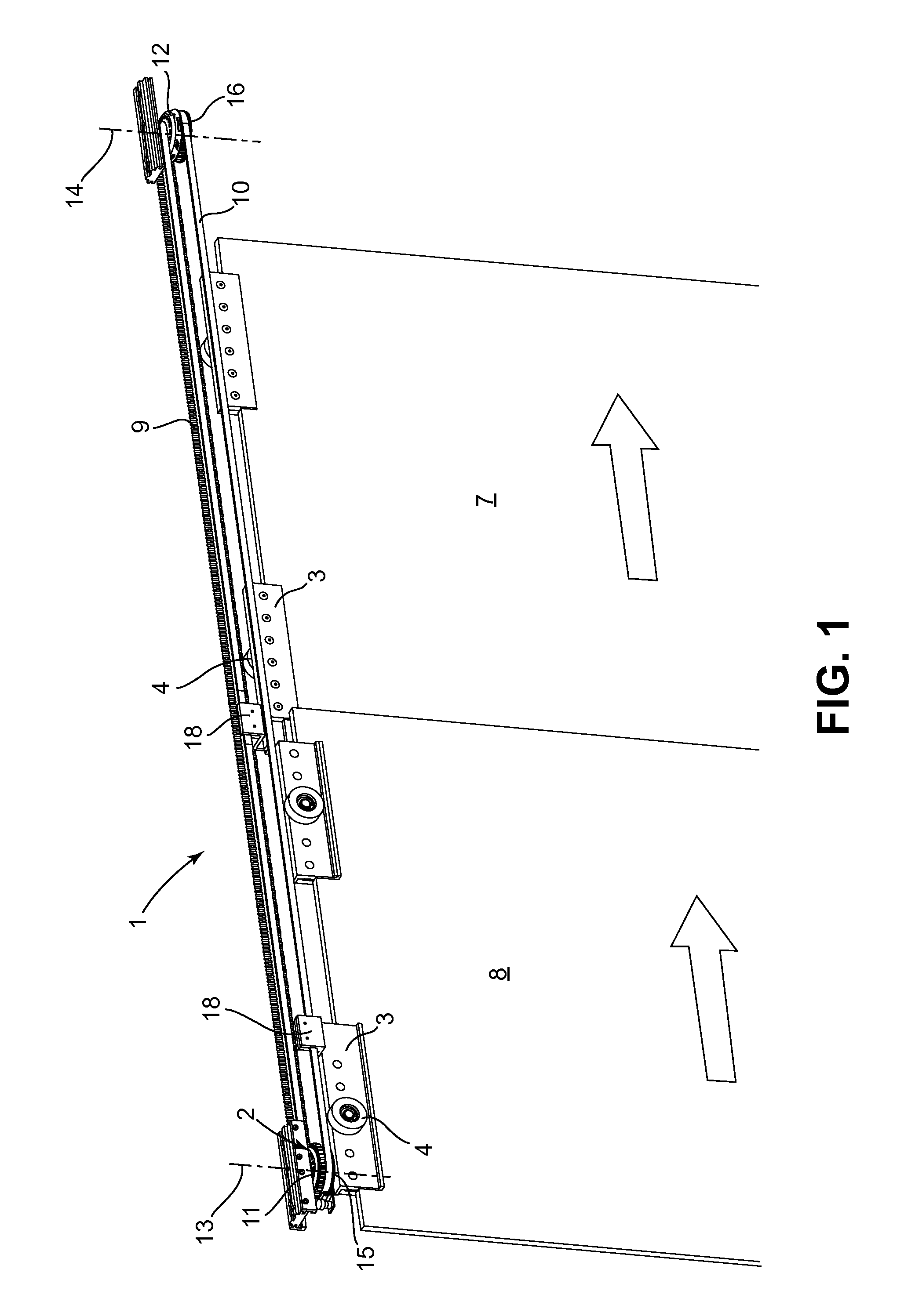
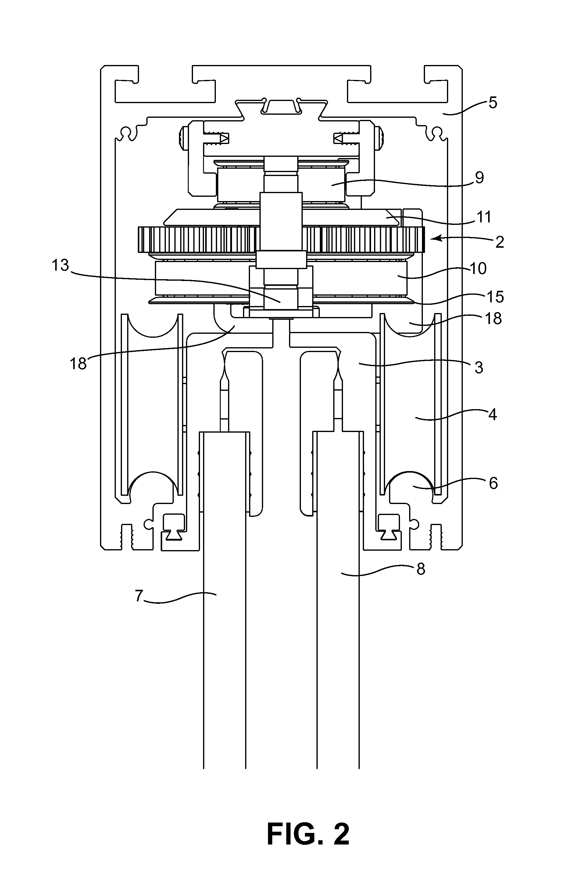
[0042]FIG. 1 shows a perspective view of the simultaneous displacement device (1) for sliding doors of the present invention according to a first preferred embodiment. As it can be seen, the sliding door has a first sliding leaf (7) and a second sliding leaf (8) hung from an upper guide (5), not shown in this figure. Both sliding leaves (7) and (8) have the ability to run in the direction of the upper guide (5), thanks to the use of fastening clamps (3) having rolling means (4) which slide on tracks (6) arranged inside said upper guide (5). FIG. 2 shows a sectional view of the upper guide (5) where it can be seen how the different components of the present invention are integrated.

[0043]Again in FIG. 1, it can be seen that the device (1) of the present invention comprises a first cogged belt (9) enabled for the union of the first sliding leaf (7). The first cogged belt (9) is established between a first set of cogged pulleys (11) and (12) which rotate freely on a first axis (13) and...


PUM


Abstract

Simultaneous displacement device for sliding doors, being a first sliding leaf (7) joined to a first cogged belt (9) established between a first set of cogged pulleys (11) and (12) which rotate freely on a first axis (13) and second axis (14) respectively, and a second sliding leaf (8) joined to a second cogged belt (10) established between a second set of cogged pulleys (15) and (16) which rotate freely on said first axis (13) and second axis (14) respectively, said device comprising clutching means (2) which enable to adopt a first position where the first cogged belt (9) and the second cogged belt (10) move independently, and a second position where the first cogged belt (9) and the second cogged belt (10) move integrally to enable the simultaneous displacement of the first sliding leaf (7) and of the second sliding leaf (8).

Description

[0001]This application claims benefit of Serial No. 200900999, filed 16 April 2009 in Spain and which application is incorporated herein by reference. To the extent appropriate, a claim of priority is made to the above disclosed application.OBJECT OF THE INVENTION[0002]The present invention refers to a simultaneous displacement device for sliding doors comprising, both two sliding leaf which slide in the same direction and sense and three and four sliding leaves which slide in the opposite direction to the two first leaves in a synchronized manner. All the main elements which configure the device are integrated in an upper guide with easy installation and mounting.[0003]The present invention is especially suitable for applying it in glass sliding doors which are manually run with respect to fixed enclosures or panels which frame an open passage area assisted by said door.BACKGROUND OF THE INVENTION[0004]There are known simultaneous displacement devices for sliding doors with only tw...

Claims


Application Information

Patent Timeline
IPC IPC(8): E06B3/46
CPCE05D15/08E05F17/002E05F17/004E05F15/643E05Y2201/62E05Y2201/652E05Y2900/132E05Y2201/216
Inventor TARREGA LLORET, MIGUEL ANGEL
Owner KLEIN IBERICA
Why Eureka
Try Eureka