Heat dissipating means for circuit-breaker and circuit-breaker with such a heat dissipating means

a heat dissipation means and circuit breaker technology, applied in the field of circuit breaker, can solve the problems of affecting the operation of the circuit breaker, and the available space of the heat sink in the circuit breaker, and achieve the effect of dissipating heat generated and maximizing the use of the available spa

Active Publication Date: 2010-11-11
ABB (SCHWEIZ) AG
View PDF7 Cites 16 Cited by
  • Summary
  • Abstract
  • Description
  • Claims
  • Application Information

AI Technical Summary

Benefits of technology

[0007]The present invention aims at providing an approach of dissipating heat generated in a CB while making more efficient

Problems solved by technology

Generally, heat generated in contacts, contact stems, and electrical conductors of a CB is disadvantages, because a high temperature raised by the heat may cause insulating elements to be worn out earlier, cause protecting electronics to function incorrectly, and even cause distortion to the contacts and contact stems, and eventually cause failure to the CB.
In practice, to dissipate heat efficiently, the size of such a heat sink should be very bi

Method used


Image

  • Heat dissipating means for circuit-breaker and circuit-breaker with such a heat dissipating means
  • Heat dissipating means for circuit-breaker and circuit-breaker with such a heat dissipating means
  • Heat dissipating means for circuit-breaker and circuit-breaker with such a heat dissipating means

Examples


Embodiment Construction

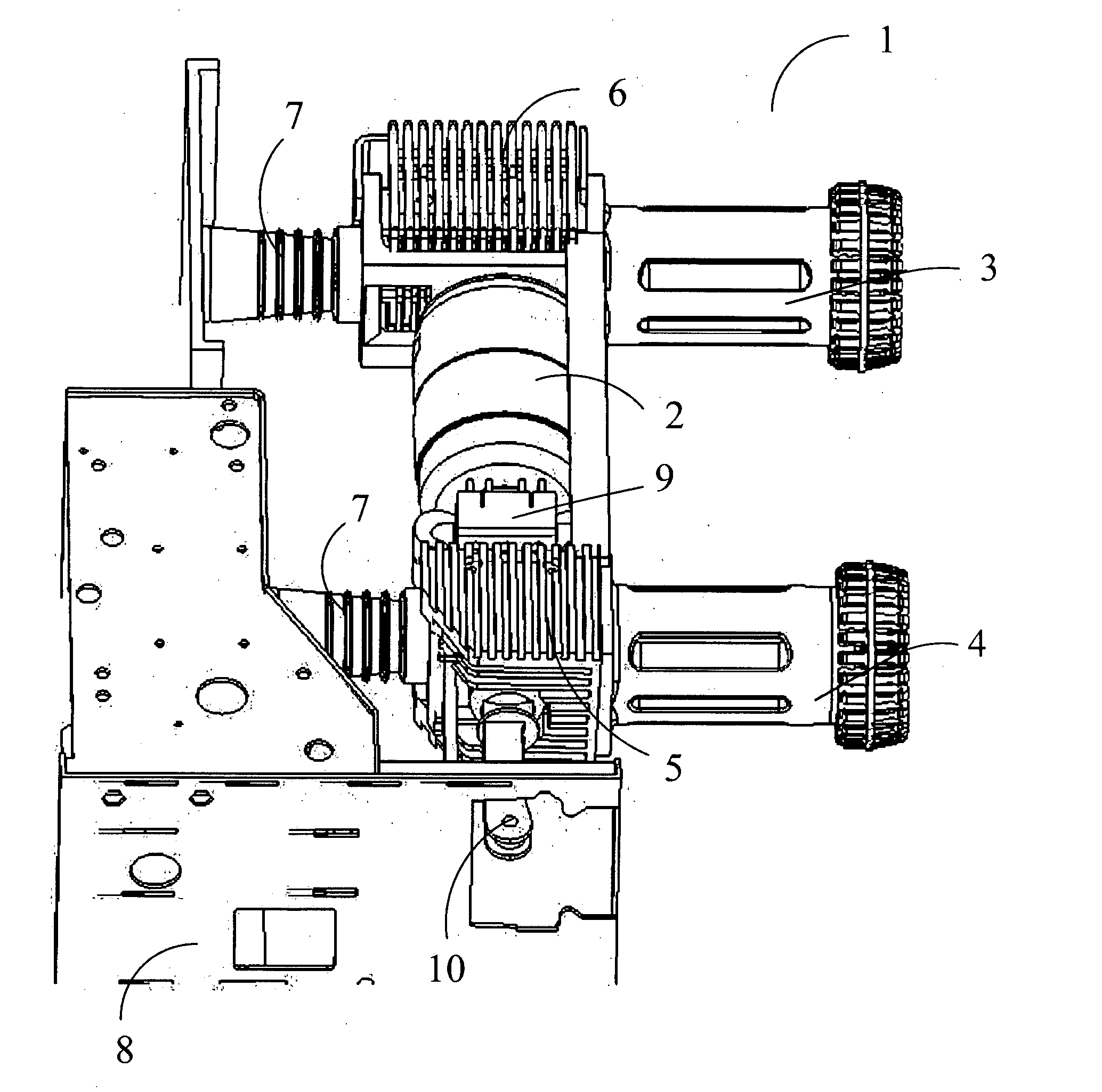
[0033]FIG. 9 shows a view of the assembly diagram of a switching device, for example, a circuit breaker (CB) 1 according to the present invention. The CB 1 comprises a vacuum chamber 2 housing a fixed contact and a movable contact (not shown) for connecting and / or interrupting a circuit. A corresponding fixed contact stem supports the fixed contact in the vacuum chamber 2 and extends outward from the upper end of the vacuum chamber 2, and a movable contact stem supports the movable contact in the vacuum chamber 2 and extends outward from the lower end of the vacuum chamber 2. The assembly of the second contact stem and the movable contact can move reciprocally in the vacuum chamber 2 to contact with and / or separate from the fixed contact. Above described is common principle for a CB, and is not shown in the drawings, but should be apparent for one skilled in the art. The CB of the present invention also comprises electrical conductors 3 and 4 for connecting the CB to a protected dev...


PUM


Abstract

The present invention discloses a circuit breaker comprising: a vacuum chamber; a fixed contact and a movable contact disposed in a vacuum chamber; a fixed contact stem supporting said fixed contact in said vacuum chamber and extending outwards from a first end of said vacuum chamber; a movable contact stem supporting said movable contact in said vacuum chamber for reciprocal movement between contact with and separated from said fixed contact, and extending outwards from a second end of said vacuum chamber; a first electrical conductor coupled to said fixed contact stem; a second electrical conductor coupled to said movable contact stem; at least one heat dissipating means disposed for at least one of said fixed contact and movable contact; wherein, the heat dissipating means is hollow and has an external surface and internal surface; a plurality of fins provided on said internal surface constitute a passage through which air is convected in a direction parallel to that of reciprocal movement of movable contact stem.

Description

TECHNICAL FIELD[0001]The present invention relates to a circuit breaker, especially a circuit breaker for medium voltage. More specifically, the present invention relates to a heat dissipating means for dissipating heat generated by current conducted through the circuit breaker.BACKGROUND ART[0002]Circuit-Breakers (CB) are well known apparatus providing overload protection for devices, especially high-power devices, like engines, lines, transformers, generators or other such things. When a current flows through a CB, heat tends to be generated due to resistance of contacts, contact stems, and electrical conductors of CB. Given the resistance as a constant, for example, R, heat generated by a current I flowing there through should be approximately I2R. In practice, the resistance R will increase along with the temperature of the contacts, the contact stems, and the electrical conductors due to the heat generated therein. Therefore, heat actually generated will be much more than that ...

Claims


Application Information

Patent Timeline
IPC IPC(8): H01H33/66
CPCH01H1/5822H01H2033/6613H01H33/6606H01H9/52
Inventor TU, ZHANWEISINGH, SHAILENDRA
Owner ABB (SCHWEIZ) AG
Why Eureka
Try Eureka