Pneumatic Blow-Down Actuator

a pneumatic blow-down actuator and actuator technology, applied in mechanical equipment, transportation and packaging, gear, etc., can solve the problems of pilots having to land on the belly, prone to accidents, and prone to failure,

Inactive Publication Date: 2010-11-11
SPECTRUM AERONAUTICAL
View PDF16 Cites 34 Cited by
  • Summary
  • Abstract
  • Description
  • Claims
  • Application Information

AI Technical Summary

Benefits of technology

[0008]In order to ensure that the landing gear is deployed, despite a failure of the electromechanical system, the linear actuator is provided with a pneumomechanical back-up system. Further the linear actuator includes a clutch for disconnecting the gear train from the motor to allow the ball screw to rotate freely. For the pneumatic system, a port is positioned on the chamber of the ball screw housing to provide fluid communication between the chamber and a pressurized fluid such as nitrogen. Further, a valve is provided to selectively open and close the fluid communication between the port and the pressurized fluid. As a result, introduction of...

Problems solved by technology

On the other hand, a retractable landing gear also introduces issues of reliability.
While electromechanical linear actuators are relatively simple and...

Method used


Image

  • Pneumatic Blow-Down Actuator
  • Pneumatic Blow-Down Actuator
  • Pneumatic Blow-Down Actuator

Examples


Embodiment Construction

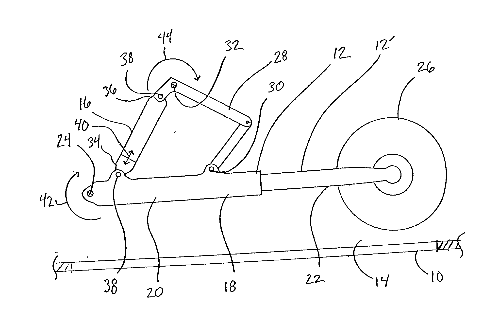
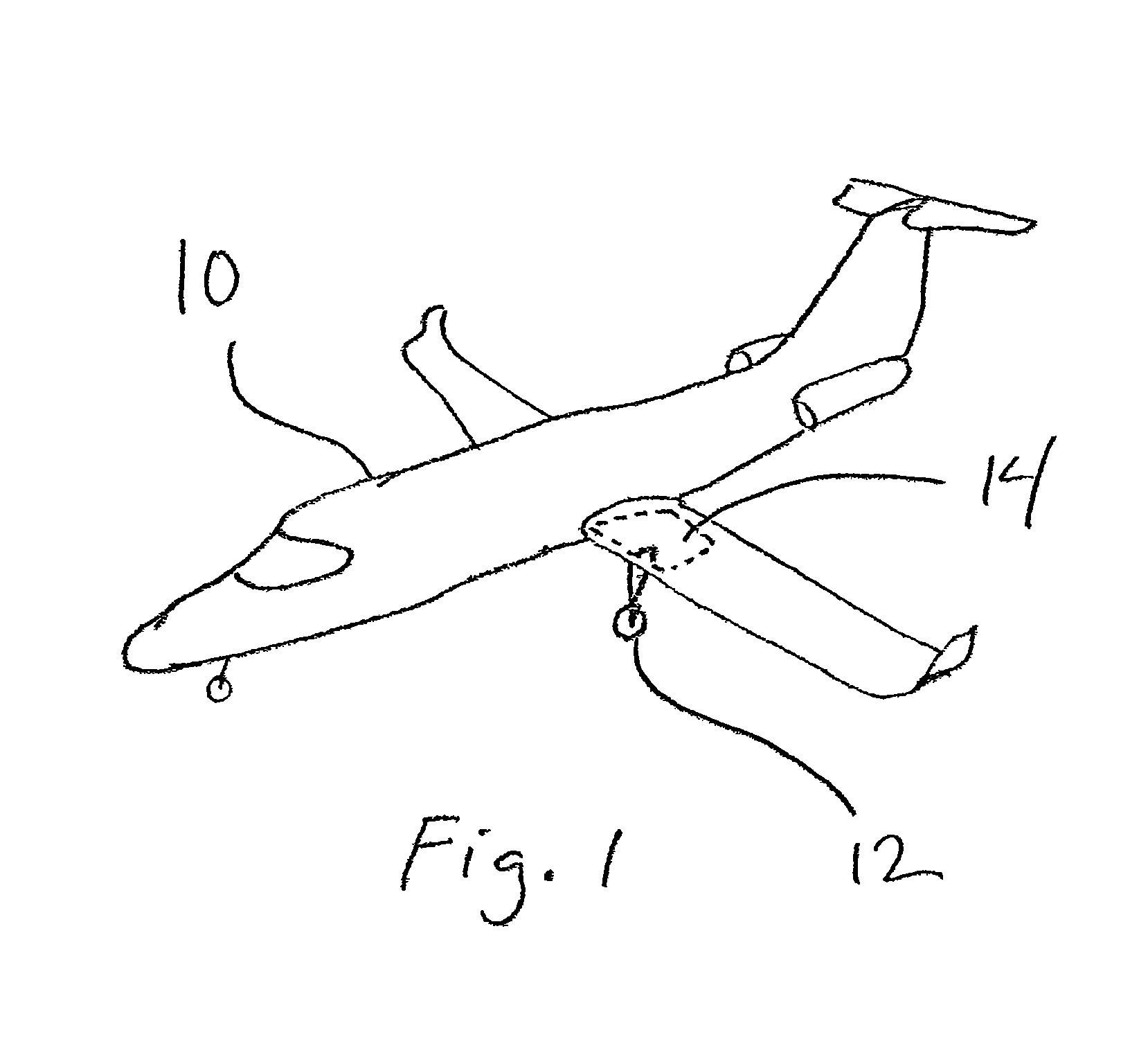
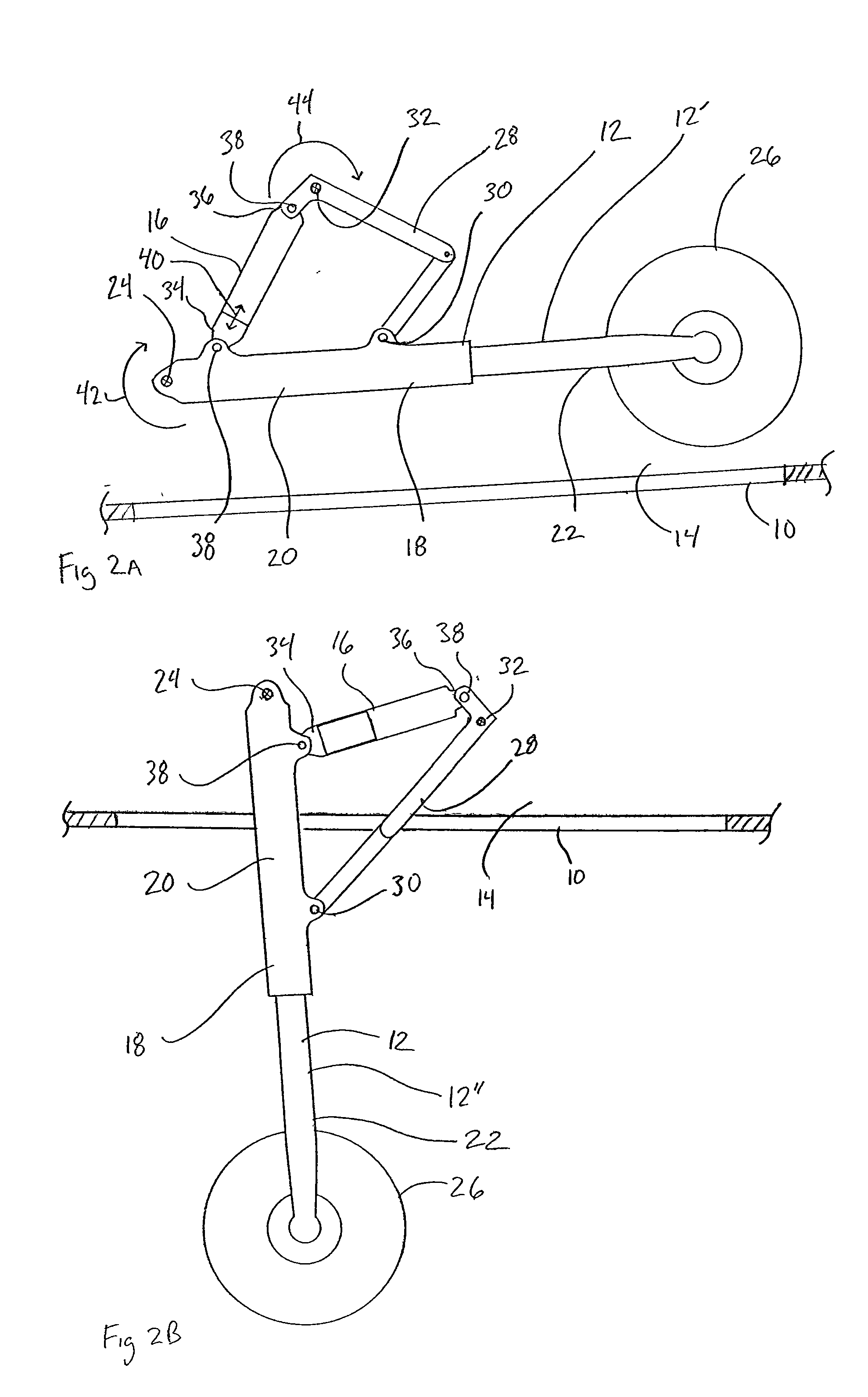
[0015]Referring initially to FIG. 1, an aircraft 10 is shown having retractable landing gear 12 extending from its gear bay 14 for landing. Referring to FIGS. 2A and 2B, an electromechanical and pneumomechanical linear actuator for extending the landing gear 12 is shown and designated 16. As shown in FIG. 2A, the landing gear 12 is in its stowed configuration 12′ within the gear bay 14. In FIG. 2B, the linear actuator 16 has extended to drive the landing gear 12 to its deployed configuration 12″ for landing.

[0016]In FIGS. 2A and 2B, exemplary landing gear 12 is illustrated to include a folding strut 18 formed with an upper end 20 and a lower end 22. Further, the upper end 20 is pivotably mounted to the gear bay 14 at a pivot 24 and the lower end 22 is mounted to a wheel assembly 26. Also, the folding strut 18 includes a hinged arm 28 that is pivotably connected both to the upper end 20 at pivot 30 and to the gear bay 14 at pivot 32. Further, the linear actuator 16 is shown to have t...


PUM


Abstract

An electromechanical linear actuator includes a pneumomechanical back-up system to ensure extension of retractable landing gear for landing an aircraft. Structurally, the linear actuator includes a stator forming a channel for receiving a ball screw. Further, the actuator includes a ball screw housing forming a chamber for receiving the ball screw. Specifically, the ball screw and the housing are in threaded engagement to translate rotation of the ball screw into axial extension of the housing. To power electromechanical extension of the actuator, the ball screw is selectively engaged to a motor with a gear train. Importantly, fluid communication between the ball screw housing and a pressurized fluid is selectively provided by a valve. If electromechanical extension of the actuator fails, the gear train is disconnected from the ball screw and the pressurized fluid is introduced into the chamber to drive pneumomechanical extension.

Description

FIELD OF THE INVENTION[0001]The present invention pertains generally to aircraft landing gear. More particularly, the present invention pertains to a linear actuator that is provided with a redundant system for powering extension. The present invention is particularly, but not exclusively, useful as an electromechanical and pneumomechanical linear actuator for deploying landing gear from an aircraft.BACKGROUND OF THE INVENTION[0002]Conventionally, fixed wing aircraft employ one of two types of landing gear: fixed landing gear and retractable landing gear. Importantly, retractable landing gear provides reduced drag on the aircraft during flight, resulting in higher speed and better fuel efficiency. On the other hand, a retractable landing gear also introduces issues of reliability. Specifically, deployment of the landing gear before touchdown is an operational necessity and is of utmost concern to the pilot.[0003]Typically, retraction and extension of a retractable landing gear is pe...

Claims


Application Information

Patent Timeline
IPC IPC(8): B64C25/18F16H25/20B64C25/26B64C25/30B64C25/22B64C25/24
CPCB64C25/18Y10T74/18592B64C25/30B64C25/22
Inventor MASON, GARTH L.
Owner SPECTRUM AERONAUTICAL
Why Eureka
Try Eureka