
Droplet-discharging apparatus, electrooptic device, electronic apparatus, and method for electrooptic device

a technology of electrooptic device and droplet, which is applied in the direction of inkjet head, wing accessories, transportation and packaging, etc., can solve the problems of high production cost, high production cost, and inability to produce high-quality nozzles in such inkjet heads, and achieve high accuracy, easy adjustment, and high accuracy

Inactive Publication Date: 2010-11-11
SEIKO EPSON CORP
View PDF12 Cites 4 Cited by
  • Summary
  • Abstract
  • Description
  • Claims
  • Application Information

AI Technical Summary

Benefits of technology

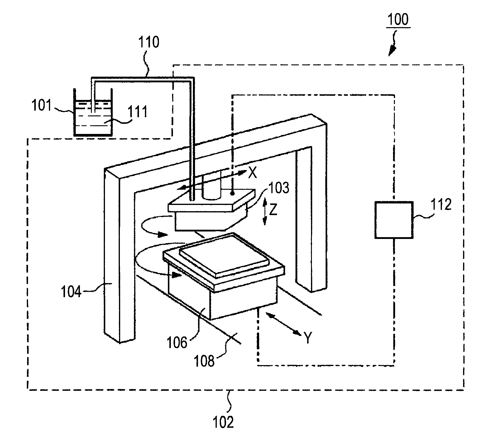
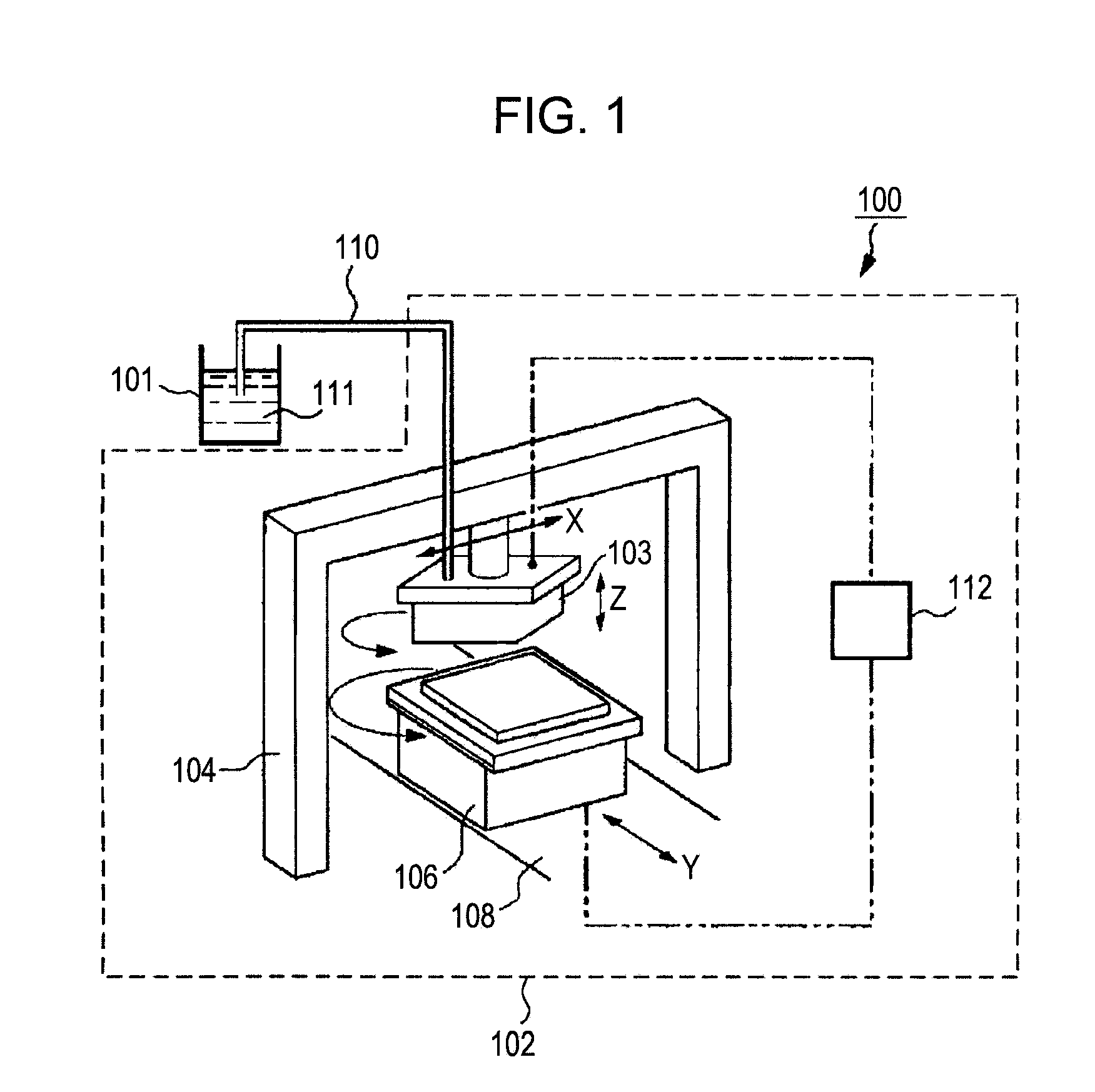
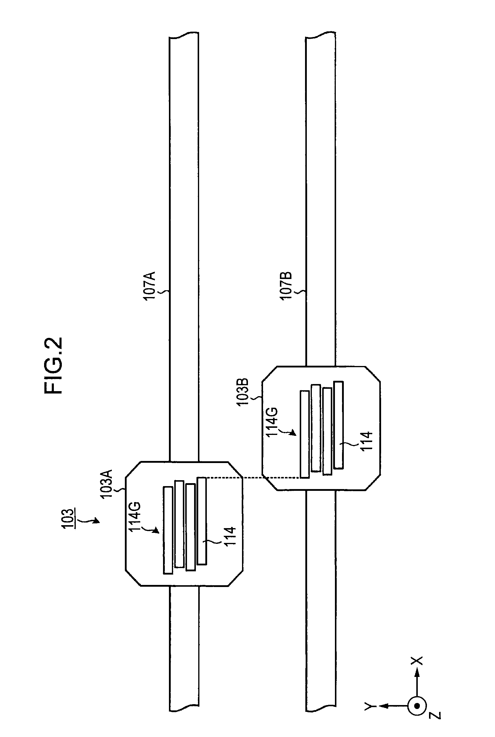
The invention is a droplet-discharging apparatus that allows for easy adjustment of the nozzle pitch and high-accuracy droplet discharging. The apparatus includes a platform for retaining a base, multiple transportation units with heads and nozzle lines, and a position-controlling unit for independently driving the transportation units. The nozzle pitch between heads can be adjusted to discharge droplets onto specific portions of the base with high accuracy. The apparatus can be used to produce electro-optical devices with high-definition images and can be incorporated into electronic apparatuses.

Problems solved by technology

However, in the spin coating, most of the liquid material supplied is splattered; hence, an excessive liquid material is required.
This is wasteful and drives the production costs up.
However, it is very difficult to produce nozzles in such an inkjet head with high accuracy.
When a desired nozzle pitch is not achieved because of low fabrication accuracy, it is necessary to disassemble and then assemble again.
That is, there is a problem with difficulty in adjusting the nozzle pitch.

Method used


Image

  • Droplet-discharging apparatus, electrooptic device, electronic apparatus, and method for electrooptic device
  • Droplet-discharging apparatus, electrooptic device, electronic apparatus, and method for electrooptic device
  • Droplet-discharging apparatus, electrooptic device, electronic apparatus, and method for electrooptic device

Examples


modification 1

(Modification 1 of Carriage)

[0123]FIGS. 10A and 10B each are a schematic view showing carriages according to a modified embodiment 1. In the above-described embodiment, the first and second carriages 103A and 103B are disposed on different feed shafts from each other. On the other hand, in Modification 1, a plurality of carriages are disposed on the same feed shaft. As shown in FIG. 10B, a carriage group 401 includes a first carriage 401A, a second carriage 401B, and a third carriage 401C. The first, second, and third carriages 401A, 401B, and 401C are disposed on the same feed shaft 402. The first, second, and third carriages 401A, 401B, and 401C have the same configuration. Their planar images each have a parallelogram shape having two sides parallel to the x-axis and two parallel sides at an angle to the y-axis.

[0124]The first, second, and third carriages 401A, 401B, and 401C each include a head group 403G. Each of the head groups 403G includes three heads 114. Each of the heads ...

modification 2

(Modification 2 of Carriage)

[0131]FIG. 11 is a schematic view showing carriages according to Modification 1. In Modification 2, two feed shafts each include a plurality of carriages. A first feed shaft 432 and a second feed shaft 442 are disposed in parallel and on the same xy-plane. A carriage group 431 includes first and second carriages 431A and 431B on the first feed shaft 432; and third and fourth carriages 441A and 441B on the second feed shaft 442.

[0132]The case in which application is performed at a scan width being four times that of one head group 403G will be described. The first position-controlling unit 104 relatively moves the first and third carriages 431A and 441A so that the nozzle pitch between the head group 403G on the first carriage 431A and the head group 403G on the third carriage 441A has a predetermined distance.

[0133]Then, the first position-controlling unit 104 relatively moves the second carriage 431B so that the nozzle pitch between the head group 403G o...


PUM


Abstract

A droplet-discharging apparatus for discharging a droplet onto a base through the nozzle of a head, the apparatus including: a platform retaining the base; a plurality of transportation units, each including a head group having at least one head with a nozzle line and each being moved in the sub-scanning direction on an axis or on a plurality of axes disposed parallel to each other; and a position-controlling unit for adjusting relative position of the adjacent head groups arranged in the main scanning direction or in the sub-scanning direction to adjust the nozzle pitch by independently driving the plurality of transportation units, wherein the droplet is discharged onto predetermined portions on the base from the head group while the transportation units are relatively moved for the platform in the main scanning direction.

Description

CROSS-REFERENCE TO RELATED APPLICATIONS[0001]This application is a divisional of U.S. patent application Ser. No. 11 / 122,310 filed on May 4, 2005. This application claims the benefit of Japanese Patent Application No. 2004-144866 filed May 14, 2004. The disclosures of the above applications are incorporated herein by reference.BACKGROUND OF THE INVENTION[0002]1. Technical Field[0003]The present invention relates to an electrooptic device, an electronic apparatus, and a droplet-discharging apparatus. In particular, the invention relates to an electrooptic device, an electronic apparatus, and a droplet-discharging apparatus for suitably applying a liquid material to periodically arranged regions in, for example, a color-filter substrate or a color-matrix display.[0004]2. Related Art[0005]Thin films have been generally formed by, for example, spin coating, which is one type of process for applying a liquid material onto a substrate to form a thin film. In this spin coating, a liquid ma...

Claims


Application Information

Patent Timeline
Patent Type & Authority Applications(United States)
IPC IPC(8): B41J29/38B41J2/01B05C5/00B05D1/26B05D7/00B41J3/54G02B5/20H05B33/10H05B33/14H10K99/00
CPCB41J3/543B41J2202/09B41J2202/20H01L51/56H01L27/3295H01L51/0004H01L51/0012H01L27/3211H10K59/35H10K59/173H10K71/13H10K59/122H10K71/191H10K71/00H10K71/20B60J1/12E05F15/70E05Y2900/55
Inventor MATSUMOTO, RYOICHIOKUSA, TAKASHIKOJIMA, KENJI
Owner SEIKO EPSON CORP
Learn More