
Measuring arrangement for an optical spectrometer

a technology of optical spectrometer and measuring arrangement, which is applied in the direction of optical radiation measurement, instruments, spectrometry/spectrophotometry/monochromators, etc., can solve the problems of inability to achieve light scattering or absorption spectroscopy conventional methods, and the difficulty of detection, so as to improve the light coupling-in and coupling-out properties.

Active Publication Date: 2010-11-11
UNIV POSTDAM
View PDF13 Cites 12 Cited by
  • Summary
  • Abstract
  • Description
  • Claims
  • Application Information

AI Technical Summary

Benefits of technology

[0008]The object of the invention is to provide a measuring arrangement for an optical spectrometer, in particular a photon density wave spectrometer, with improved light coupling-in and coupling-out properties.
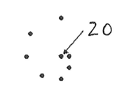
[0011]It was found, surprisingly, that the spiral-shaped arrangement of the outputs of the plurality of optical waveguide elements particularly supports efficient coupling-in of the excitation light and efficient coupling-out of the measurement light. Crosstalk effects between the plurality of optical waveguide elements are minimized Furthermore, the proposed arrangement of the plurality of optical waveguide elements supports a minimally disturbed light propagation in the sample to be measured by the optical waveguide or waveguides, which couple-in the excitation light, to the optical waveguide or waveguides which receive the measurement light. In this way the number of optical waveguides used can be increased, so that a large range of accessible distances is produced, with the result that it can be used for samples with very different optical properties.
[0015]In an advantageous variant of the invention, it can be provided that the outputs of the plurality of optical waveguide elements are fixed in their position relative to one another at least for the at least one measurement configuration. The fixing of the outputs of the plurality of optical waveguide elements relative to one another can be designed to be permanent. Alternatively it can be envisaged that the outputs of the plurality of optical waveguide elements are movable relative to one another, for example by displacement, so that the relative positions between different measurements or even for different measuring steps within a measurement can be newly set, but are then in a fixed position. A displacement relative to one another of the outputs of the plurality of optical waveguide elements can for example be carried out by means of suitable translation slides, which in embodiments that are known per se can also achieve the necessary precision of said relative displacement.
[0016]An advantageous embodiment of the invention provides that at least one part of the outputs of the plurality of optical waveguide elements is arranged in the measuring chamber. This makes it possible for the part of the outputs of the plurality of optical waveguide elements that is arranged in the measuring chamber, is even immersed in the sample to be investigated, which can additionally be influenced in that the degree of filling of the measuring chamber is adjusted depending on the application. This can be provided for some or all of the outputs arranged in the measuring chamber, depending on the measuring task.
[0019]Another embodiment of the invention can envisage that the optical waveguides are formed from optical waveguides with a graded-index profile. The use of optical waveguides with a graded-index profile makes it possible to reduce demodulation and hence improve the measurement light quality at higher frequencies of light modulation or the use of longer optical waveguides.
[0021]In an advantageous embodiment of the invention it can be envisaged that the optical waveguides are produced according to at least one of the following designs: deuterated optical waveguides and fluorinated optical waveguides. The use of fibre-optic conductors with deuteration and / or a fluorination makes it possible to reduce absorption and therefore they can be used in a wider spectral range. Moreover, the reduced surface energy of fluorinated materials leads to less soiling of the optical waveguide and easier cleaning.

Problems solved by technology

Spectroscopic investigations with photon density waves permit the separate absolute determination of absorption and scattering properties of strongly scattering samples, which is not possible with conventional methods of light scattering or of absorption spectroscopy.
On the other hand, when there is strong absorption the photon density decreases so much that detection is difficult.

Method used


Image

  • Measuring arrangement for an optical spectrometer
  • Measuring arrangement for an optical spectrometer

Examples


Embodiment Construction

OF THE INVENTION

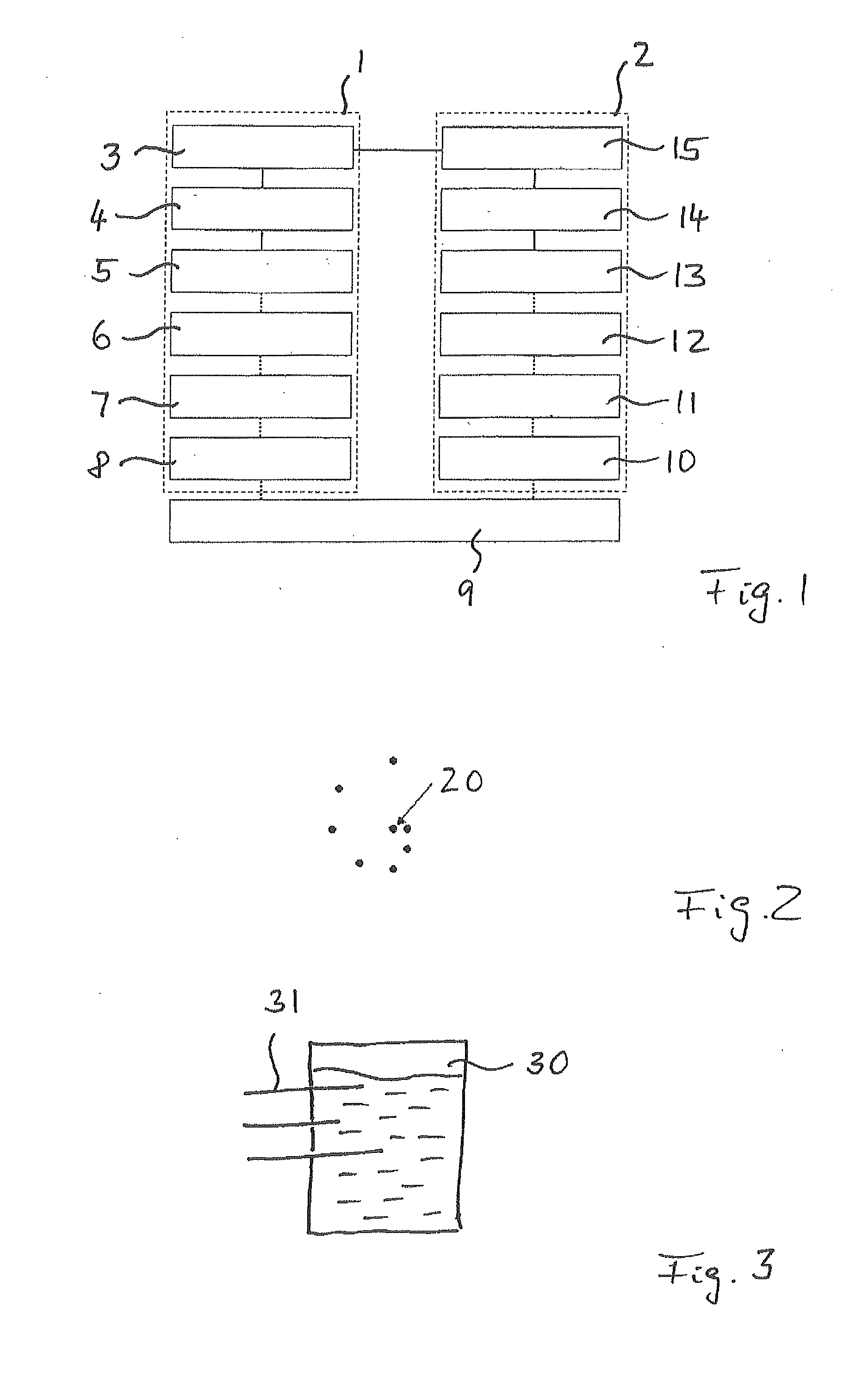
[0023]The invention is explained in more detail below, based on preferred examples, referring to the diagrams in a drawing, showing:

[0024]FIG. 1 a schematic representation of a measuring instrument using a photon density wave spectrometer,

[0025]FIG. 2 a spiral-shaped arrangement of outputs of a plurality of optical waveguide elements in the viewing direction towards the outputs and

[0026]FIG. 3 a schematic representation with a measuring chamber and a plurality of optical waveguide elements, whose outputs are arranged in the measuring chamber.

[0027]FIG. 1 shows a schematic representation of a measuring instrument using a photon density wave spectrometer (PDW-spectrometer). The dotted lines between the boxes relate to the transfer of optical signals, and continuous lines between the boxes relate to the transfer of electrical signals.

[0028]The measuring instrument is divided conceptually into two parts, namely an emission unit 1 and a detection unit 2. By means of the e...


PUM


Abstract

The invention relates to a measuring arrangement for an optical spectrometer, in particular a photon density wave spectrometer, having a measuring chamber, which can be loaded with a sample to be measured, and a coupling-in / coupling-out device which is configured to receive excitation light from a light source and couple it into the sample to be measured in the measuring chamber and to receive measuring light formed in the sample to be measured on account of the excitation light which has been coupled in and to emit said measuring light to a detection device, wherein the coupling-in / coupling-out device has an optical switching device and a plurality of light guide elements which couple to the latter, have a respective optical waveguide and can be connected according to at least one selectable measuring configuration using the optical switching device in order to couple in the excitation light and receive the measuring light according to the at least one selectable measuring configuration, and wherein outputs of the plurality of light guide elements are positioned according to a spiral arrangement in the viewing direction of the outputs.

Description

[0001]The invention relates to a measuring arrangement for an optical spectrometer, in particular a photon density wave spectrometer.BACKGROUND OF THE INVENTION[0002]Spectrometers are generally measuring or analysis devices for the spectroscopic investigation of a sample. Optical spectrometers use light for the spectroscopic investigation. Spectroscopic investigations with photon density waves permit the separate absolute determination of absorption and scattering properties of strongly scattering samples, which is not possible with conventional methods of light scattering or of absorption spectroscopy. The term “photon density waves” means the time- and space-dependent propagation of light in a strongly scattering medium, which is characterized by the number of photons per volume, i.e. the photon density.[0003]The description of photon propagation is based on investigations of the transport of neutrons, as both photons and neutrons are uncharged and, apart from scattering processes...

Claims


Application Information

Patent Timeline
IPC IPC(8): G01J3/30
CPCA61B5/0059G01J3/02G01J3/44G01J3/0297G01J3/0218
Inventor REICH, OLIVERLOHMANNSROBEN, HANS-GERD
Owner UNIV POSTDAM
Learn More