Gas bearing spindle
a technology of gas bearings and spindles, which is applied in the direction of bearings, bearings, shafts, etc., can solve the problems of difficult support of rotation shafts, and achieve the effect of preventing deviation of retaining rings
- Summary
- Abstract
- Description
- Claims
- Application Information
AI Technical Summary
Benefits of technology
Problems solved by technology
Method used
Image
Examples
first embodiment
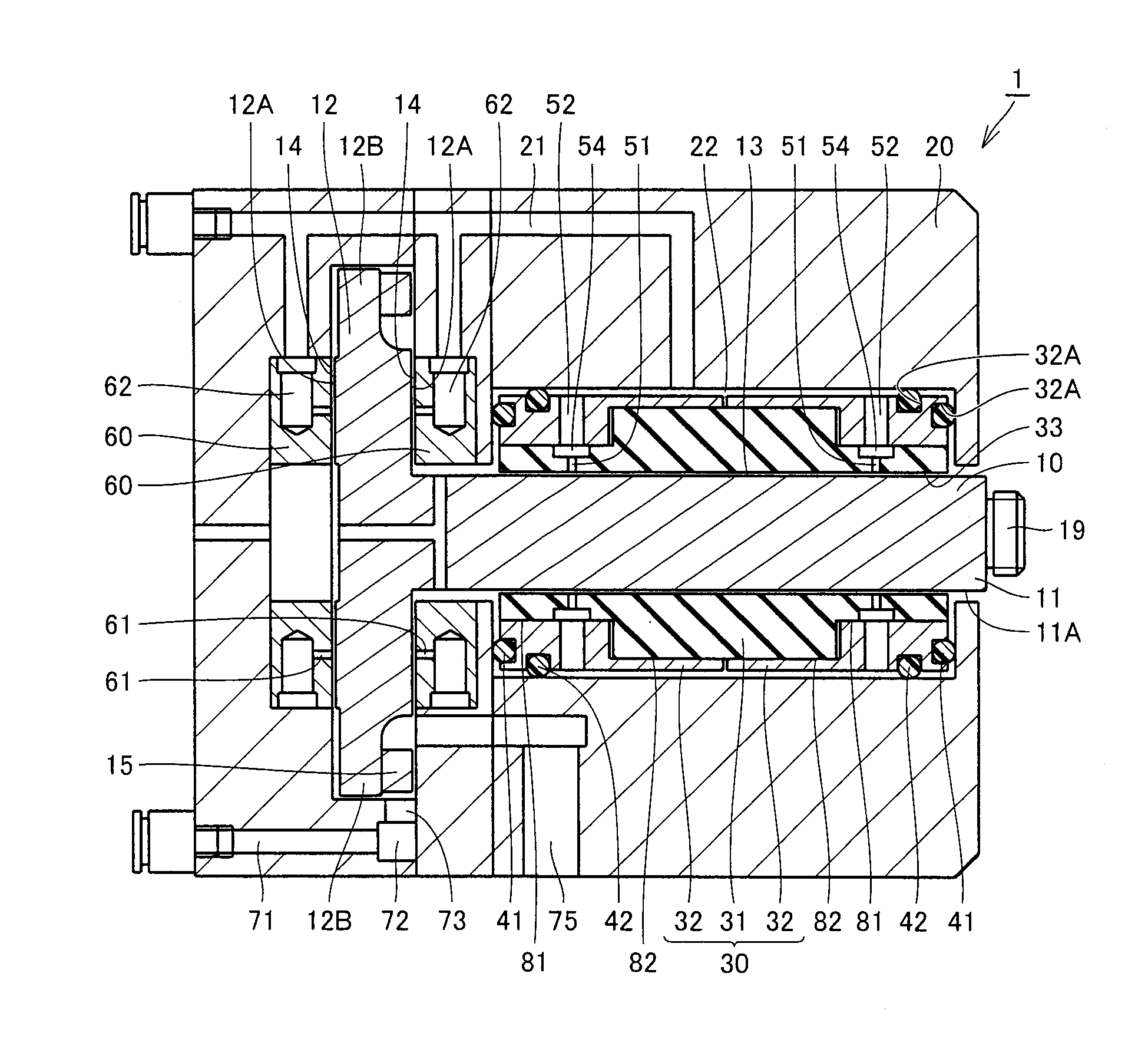
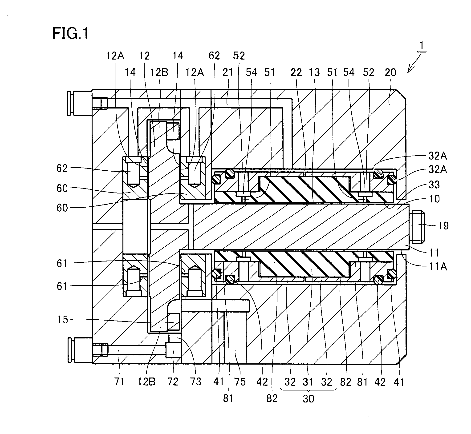
[0049]First, one embodiment of the present invention, a first embodiment, will be described. Referring to FIG. 1, a gas bearing spindle 1 in the first embodiment includes a rotation shaft 10; a sleeve 30 having a sleeve through hole 33, which is a cylindrical through hole that surrounds a portion of an outer circumferential surface 11A of rotation shaft 10; and a housing 20 surrounding sleeve 30 to retain sleeve 30 by means of O rings 41, 42 each serving as an elastic member and formed of a rubber. Rotation shaft 10 and sleeve 30 are disposed with a journal bearing clearance 13 of approximately 10 μm or greater but approximately 40 μm or smaller therebetween.
[0050]Rotation shaft 10 has a shaft portion 11 cylindrical in shape; and a flange portion 12 formed in one end of shaft portion 11 and having a large disk-like shape with a diameter larger than that of shaft portion 11. In the other end of shaft portion 11, a retaining unit 19 is formed to retain a tool or the like. Sleeve 30 is...
second embodiment
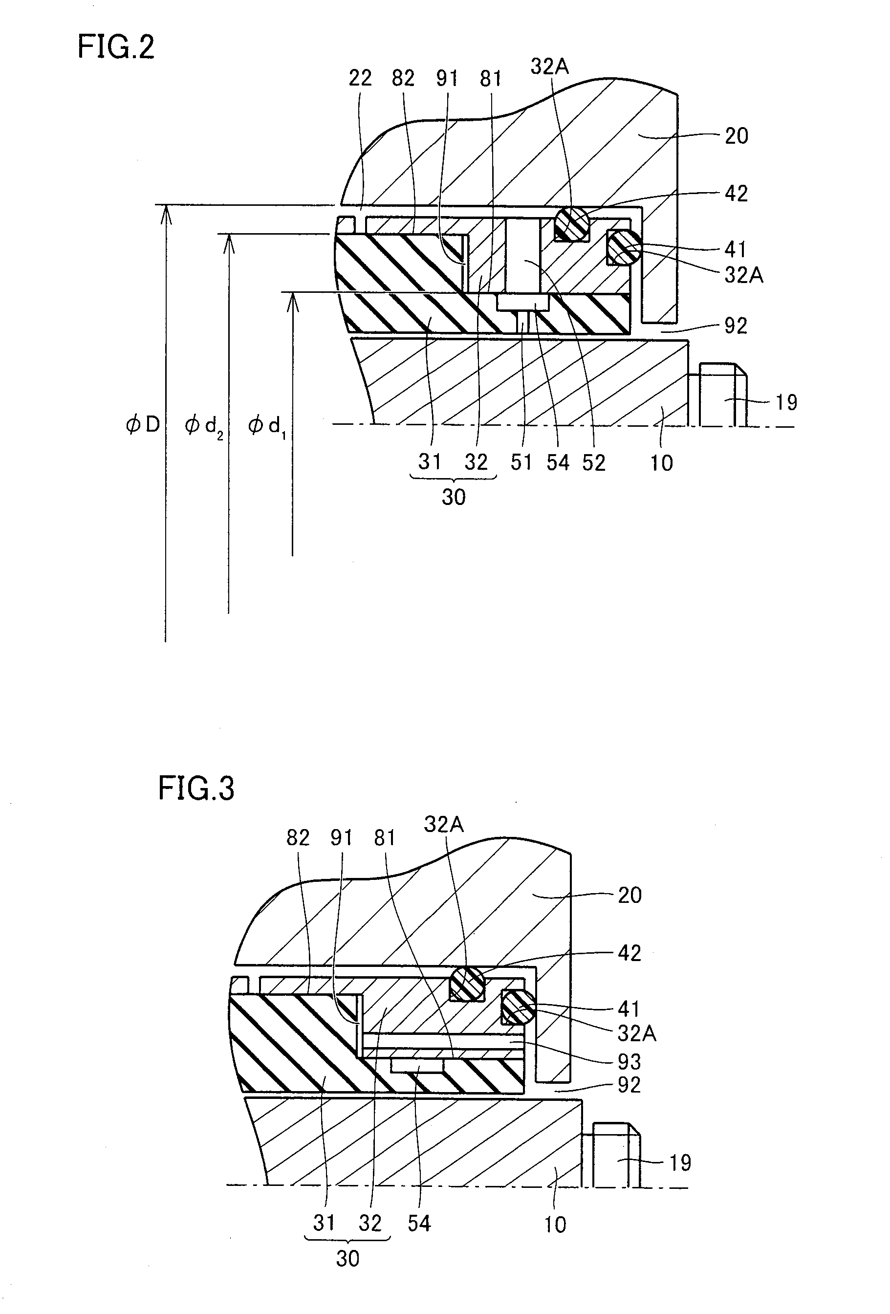
[0068]The following describes another embodiment of the present invention, a second embodiment. A gas bearing spindle 1 of the second embodiment has a configuration basically the same as that of gas bearing spindle 1 of the first embodiment, operates in a similar manner, and provides a similar effect. However, referring to FIG. 3, gas bearing spindle 1 of the second embodiment is different from gas bearing spindle 1 of the first embodiment in that a gas discharge path 93 is formed therein.
[0069]Specifically, in gas bearing spindle 1 of the second embodiment, a sleeve 30 is provided with gas discharge path 93 for connecting a boundary portion between each retaining ring 32 and a bearing portion 31 to a region located in gas bearing spindle 1 and open to external atmosphere. Via the boundary portion, a first fit surface 81 and second fit surfaces 82 are connected to one another. As described above, bearing portion 31 and retaining rings 32 are engaged with first fit surface 81 and sec...
third embodiment
[0071]The following describes still another embodiment of the present invention, a third embodiment. A gas bearing spindle 1 of the third embodiment has a configuration basically the same as that of gas bearing spindle 1 of the first embodiment, operates in a similar manner, and provides a similar effect. However, referring to FIG. 4, gas bearing spindle 1 of the third embodiment is different from gas bearing spindle 1 of the first embodiment in that a fit portion clearance 91 existing to connect first fit surface 81 and second fit surfaces 82 in sleeve 30 to one another is filled with a molding material 96 such as an adhesive agent.
[0072]Namely, in gas bearing spindle 1 of the third embodiment, the boundary portion between each retaining ring 32 and bearing portion 31, i.e., portion via which first fit surface 81 and each second fit surface 82 are connected to each other is filled with molding material 96.
[0073]Since the small fit portion clearance 91 exists in the boundary portion...
PUM
 Abstract
Description
Claims
Application Information
 - R&D
- Intellectual Property
- Life Sciences
- Materials
- Tech Scout
- Unparalleled Data Quality
- Higher Quality Content
- 60% Fewer Hallucinations
Browse by: Latest US Patents, China's latest patents, Technical Efficacy Thesaurus, Application Domain, Technology Topic, Popular Technical Reports.
© 2025 PatSnap. All rights reserved.Legal|Privacy policy|Modern Slavery Act Transparency Statement|Sitemap|About US| Contact US: help@patsnap.com


