System And Method For Tunable Chromatic Dispersion Compensation

a chromatic dispersion compensation and chromatic dispersion technology, applied in the field of fiber optic networks, can solve the problems of increased bit error rate, residual dispersion that is not corrected, and controlled wavelengths

Inactive Publication Date: 2010-11-11
II VI DELAWARE INC
View PDF14 Cites 9 Cited by
  • Summary
  • Abstract
  • Description
  • Claims
  • Application Information

AI Technical Summary

Benefits of technology

[0010]One advantage of the disclosed line node is that, since reference and data signals propagate through each amplifier, the reference signals used to measure chromatic dispersion receive the same dispersion compensation (and will have the same residual dispersion) as the data signals. Consequently, any residual dispersion in the data signals will manifest itself in downstream dispersion measurements and, thus, can be corrected. The dispersion compensator in each line node may be set to compensate for the measured dispersion, thereby compensating for both the chromatic dispersion of the link connecting the current node to the prior node and any uncorrected residual dispersion from prior nodes.

Problems solved by technology

This phenomenon, known as “pulse spreading,” can cause increased bit error rates if the light pulses spread to a point where they begin to overlap with one another.
One drawback to this approach, however, is that dispersion compensators have finite resolution, which may result in residual dispersion that is not corrected.
Another drawback is that OSC lasers typically have poorly controlled wavelengths, leading to general inaccuracies.
This problem can be addressed by using more precise lasers at each node, but such a solution is expensive and does not necessarily ensure that there will be no residual dispersion.
Again, if any residual dispersion exists at the nodes, then the dispersion accumulation problem may still persist, increasing bit rate errors.

Method used


Image

  • System And Method For Tunable Chromatic Dispersion Compensation
  • System And Method For Tunable Chromatic Dispersion Compensation
  • System And Method For Tunable Chromatic Dispersion Compensation

Examples


Embodiment Construction

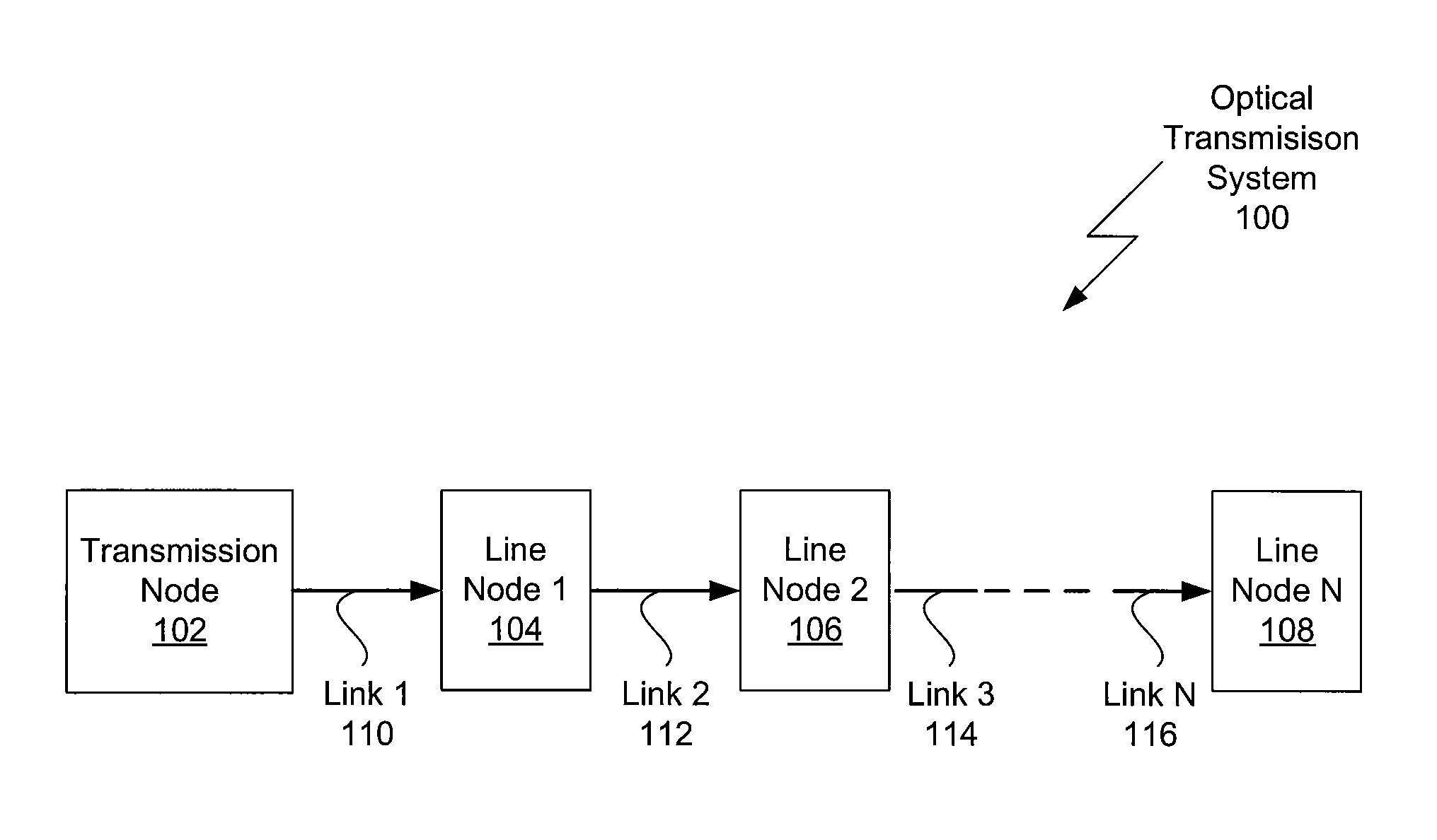
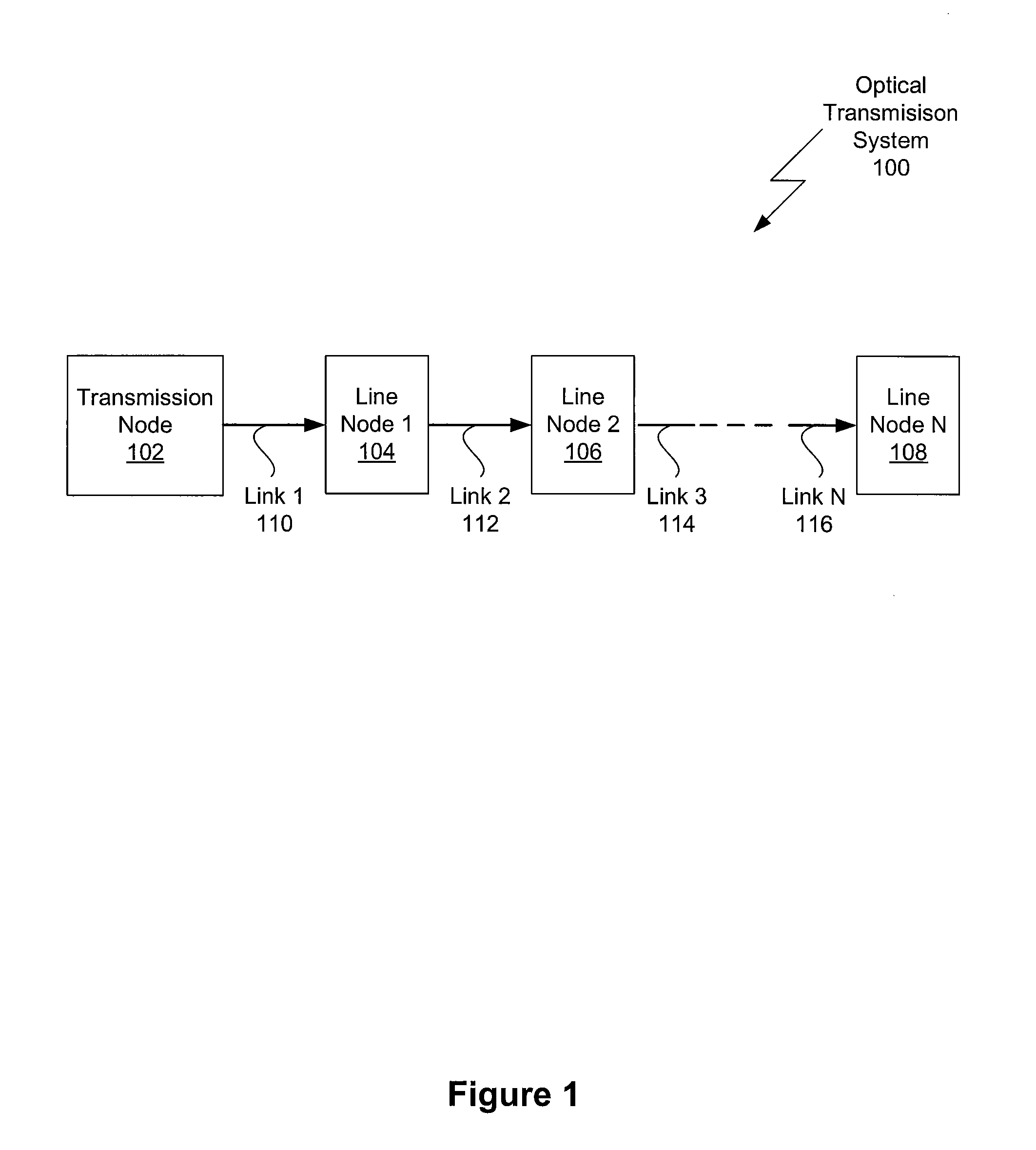
[0017]FIG. 1 depicts an optical transmission system 100 in which one or more aspects of the invention may be implemented. As shown, the optical transmission system 100 includes, without limitation, a transmission node 102, a line node 1104, a line node 2106, and a line node N 108. The optical transmission system 100 also includes a link 1110 between the transmission node 102 and the line node 1104, a link 2112 between the line node 1104 and the line node 2106, a link 3114 between the line node 3106 and the next line node in the system, and a link N 116 between the next-to-last node in the system and the line node N 108. The transmission node 102 is a terminal node and is configured to generate and transmit optical signals through the link 1110 to the line node 1104. The line node 1104 is configured to receive the optical signals through the link 1110, regenerate these optical signals, and send these regenerated signals through the link 2112. The line node 2106 is configured to recei...


PUM


Abstract

One embodiment sets forth a technique for measuring chromatic dispersion using reference signals within the operational range of amplifiers used to refresh data signals. One red / blue laser pair in the transmission node is used for measuring dispersion and chromatic dispersion compensation is added at each line node in the system. Since reference and data signals propagate through each amplifier, the reference signals used to measure chromatic dispersion receive the same dispersion compensation (and will have the same residual dispersion) as the data signals. Therefore, any residual dispersion in the data signals will manifest itself in downstream dispersion measurements and, thus, can be corrected. The tunable dispersion compensator in each line node may be set to compensate for the measured dispersion, thereby compensating for both the chromatic dispersion of the link connecting the current node to the prior node and any uncorrected residual dispersion from prior nodes.

Description

BACKGROUND OF THE INVENTION[0001]1. Field of the Invention[0002]The present invention relates generally to the field of fiber optic networks and more specifically to a system and method for tunable chromatic dispersion compensation.[0003]2. Description of the Related Art[0004]A typical fiber optic communication system includes transmission nodes, line nodes, and links. Transmission nodes are terminal nodes that include optical signal sources, such as a laser. Line nodes typically include optical amplifiers, couplers, and decouplers. In many common applications, the line nodes also include other devices, such as chromatic dispersion compensators. Links are used to convey optical signals between nodes.[0005]Lasers that transmit optical signals on links, such as optical fibers, provide a narrow spectrum of light (i.e., a light pulse) that includes many wavelengths. Chromatic dispersion is a variation in the velocity of this signal according to wavelength. Among other things, this varia...

Claims


Application Information

Patent Timeline
Patent Type & Authority Applications(United States)
IPC IPC(8): H04B10/00
CPCH04B10/2513
Inventor LIN, CHRISTOPHERSUMMA, MARKWILLIAMS, MARTINBUTLER, DOUGLASWIGLEY, PETER
Owner II VI DELAWARE INC
Why Eureka
Try Eureka