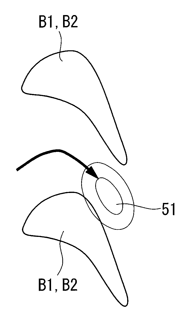
Turbine blade cascade endwall
a turbine blade and cascade technology, applied in the direction of liquid fuel engines, vessel construction, marine propulsion, etc., can solve the problems of reducing the overall performance of a turbine having a plurality of blade cascades, and achieve the effects of enhancing overall turbine performance, reducing secondary-flow loss, and reducing crossflow
- Summary
- Abstract
- Description
- Claims
- Application Information
AI Technical Summary
Benefits of technology
Problems solved by technology
Method used
Image
Examples
first embodiment
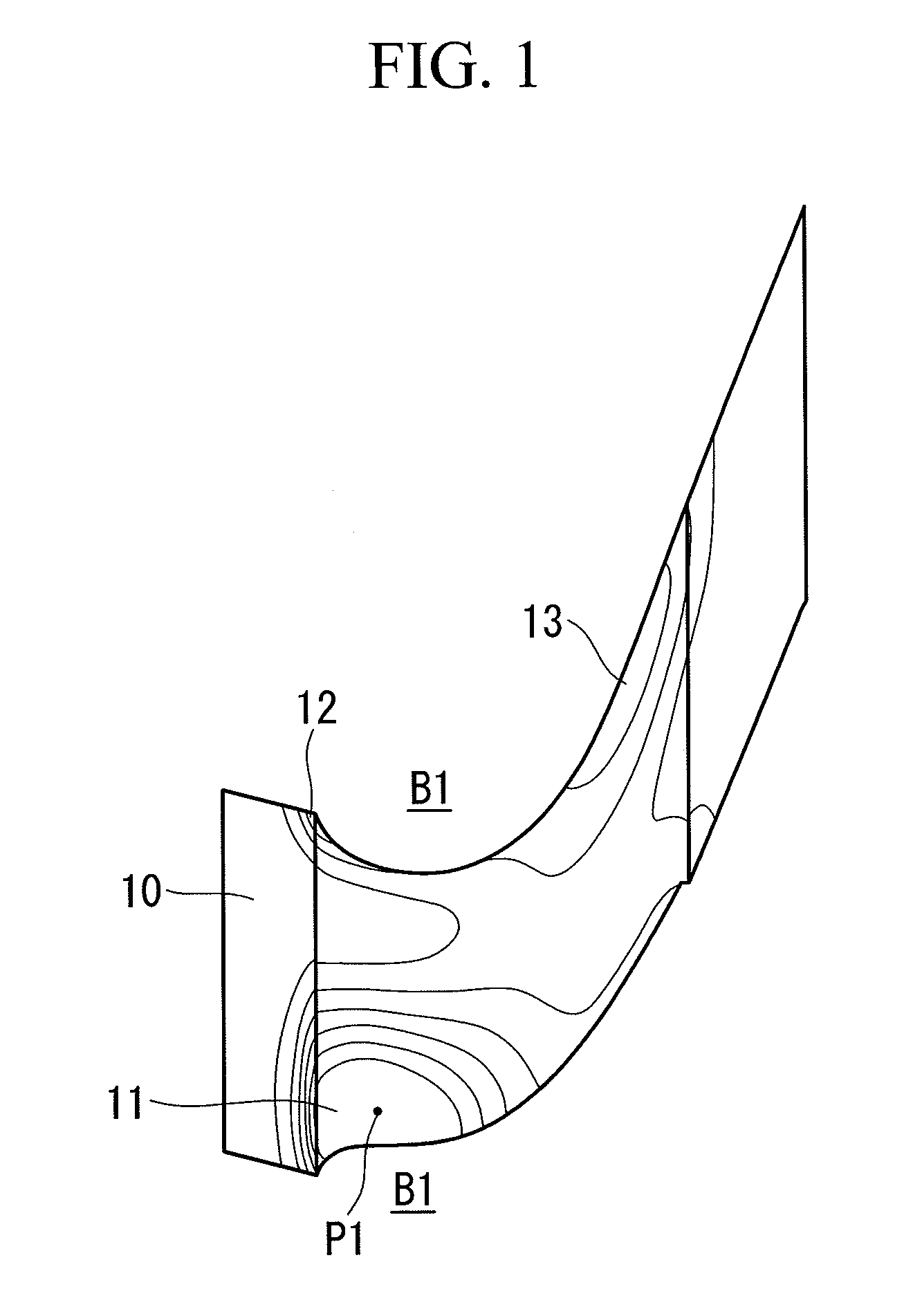
[0024]a turbine blade cascade endwall according to the present invention will be described below, with reference to FIG. 1.
[0025]As shown in FIG. 1, each turbine blade cascade endwall (hereinafter, referred to as “third-stage stationary-blade tip endwall) 10 according to this embodiment has a first convex portion 11 between one turbine third-stage stationary blade (hereinafter, referred to as “third-stage stationary blade”) B1 and another third-stage stationary blade B1 disposed adjacent to this third-stage stationary blade B1.
[0026]Note that, solid lines drawn on the third-stage stationary-blade tip endwall 10 in FIG. 1 indicate contour lines of the first convex portion 11, contour lines of a second convex portion 12, to be described later, and contour lines of a third convex portion 13, to be described later.
[0027]The first convex portion 11 has an apex (peak) P1 at a position of 0 to 20% pitch (substantially 7% pitch in this embodiment) at a position of 5 to 25% Cax (substantiall...
second embodiment
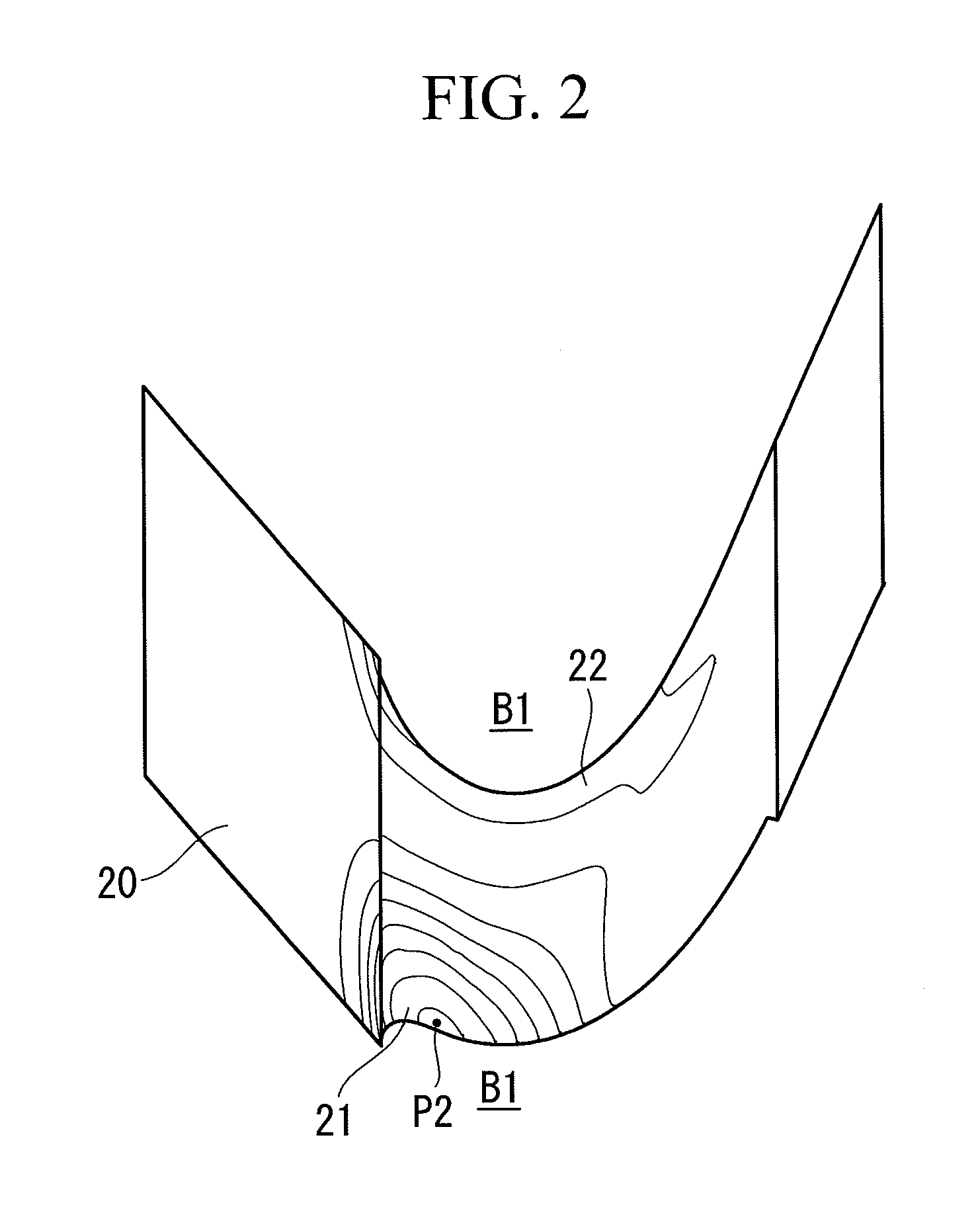
[0032]a turbine blade cascade endwall according to the present invention will be described with reference to FIG. 2.
[0033]As shown in FIG. 2, each turbine blade cascade endwall (hereinafter, referred to as “third-stage stationary-blade hub endwall) 20 according to this embodiment has a fourth convex portion 21 between one turbine third-stage stationary blade (hereinafter, referred to as “third-stage stationary blade”) B1 and another third-stage stationary blade B1 disposed adjacent to this third-stage stationary blade B1. Note that, solid lines drawn on the third-stage stationary-blade hub endwall 20 in FIG. 2 indicate contour lines of the fourth convex portion 21 and contour lines of a fifth convex portion 22, to be described later.
[0034]The fourth convex portion 21 has an apex (peak) P2 at a position of 0 to 20% pitch (substantially 3% pitch in this embodiment) at a position of 5 to 25% Cax (substantially 14% Cax in this embodiment) and is, as a whole, a gently (smoothly) swollen ...
third embodiment
[0038]a turbine blade cascade endwall according to the present invention will be described with reference to FIG. 3.
[0039]As shown in FIG. 3, each turbine blade cascade endwall (hereinafter, referred to as “fourth-stage stationary-blade tip endwall) 30 according to this embodiment has a first concave portion 31 between one turbine fourth-stage turbine stationary blade (hereinafter, referred to as “fourth-stage stationary blade”) B2 and another fourth-stage stationary blade B2 disposed adjacent to this fourth-stage stationary blade B2. Note that, solid lines drawn on the fourth-stage stationary-blade tip endwall 30 in FIG. 3 indicate isobathic lines of the first concave portion 31 and isobathic lines of a sixth convex portion 32, to be described later.
[0040]The first concave portion 31 has a bottom point (depression peak) P3 at a position of 70 to 90% pitch (substantially 83% pitch in this embodiment) at a position of 5 to 25% Cax (substantially 17% Cax in this embodiment) and is, as...
PUM
 Abstract
Description
Claims
Application Information
 - R&D
- Intellectual Property
- Life Sciences
- Materials
- Tech Scout
- Unparalleled Data Quality
- Higher Quality Content
- 60% Fewer Hallucinations
Browse by: Latest US Patents, China's latest patents, Technical Efficacy Thesaurus, Application Domain, Technology Topic, Popular Technical Reports.
© 2025 PatSnap. All rights reserved.Legal|Privacy policy|Modern Slavery Act Transparency Statement|Sitemap|About US| Contact US: help@patsnap.com


