
Dual Energy Therapy Needle

a needle and energy therapy technology, applied in the field of dual energy therapy needles, can solve the problems of ineffective treatment, insufficient power density for fast and reliable volumetric ablation in target tissue, and insufficient needle insertion for

Inactive Publication Date: 2010-11-11
GYNESONICS
View PDF9 Cites 39 Cited by
  • Summary
  • Abstract
  • Description
  • Claims
  • Application Information

AI Technical Summary

Benefits of technology

The present invention is about using an inductively tuned radiating slot microwave antenna to produce spherical coagulative volumes in tissue. The invention provides a dual energy therapy needle that combines a microwave antenna with an electric cutting device. The microwave antenna can operate at different frequencies and power levels to produce coagulative ablation of target tissue with a diameter of 1 to 4 centimeters. The methods of treating tissue can include positioning the microwave needle at the target tissue, cutting into the tissue with the electric cutting device, and applying microwave energy to produce a coagulative volumetric ablation. The target tissues can include uterine fibroids, prostate hyperplasia or cancer, liver cancer, malignant bone and soft tissue sarcoma, and internal bleeding.

Problems solved by technology

Microwave antennas or needles have been contemplated to treat the various pathological conditions described herein, but have been ineffective forms of treatment.
The challenges of using a microwave applicator include applicator geometry, where diameters are too large to access target tissue, and efficiency, where microwave applicators are not designed with a good match into high water content tissue and as a result they do not effectively produce the power density required for fast and reliable volumetric ablation in target tissue.
Additionally, as the tissue density of the tissue to be treated increases, incremental increases in needle insertion forces are required to position a medical applicator within tissue at a desired location or depth.
Furthermore, increased insertion forces can result in displacing the position of a tissue mass leading to additional complications.

Method used


Image

  • Dual Energy Therapy Needle
  • Dual Energy Therapy Needle
  • Dual Energy Therapy Needle

Examples


Embodiment Construction

[0028]Certain specific details are set forth in the following description and figures to provide an understanding of various embodiments of the invention. Certain well-known details, associated electronics and devices are not set forth in the following disclosure to avoid unnecessarily obscuring the various embodiments of the invention. Further, those of ordinary skill in the relevant art will understand that they can practice other embodiments of the invention without one or more of the details described below. Finally, while various processes are described with reference to steps and sequences in the following disclosure, the description is for providing a clear implementation of particular embodiments of the invention, and the steps and sequences of steps should not be taken as required to practice this invention.

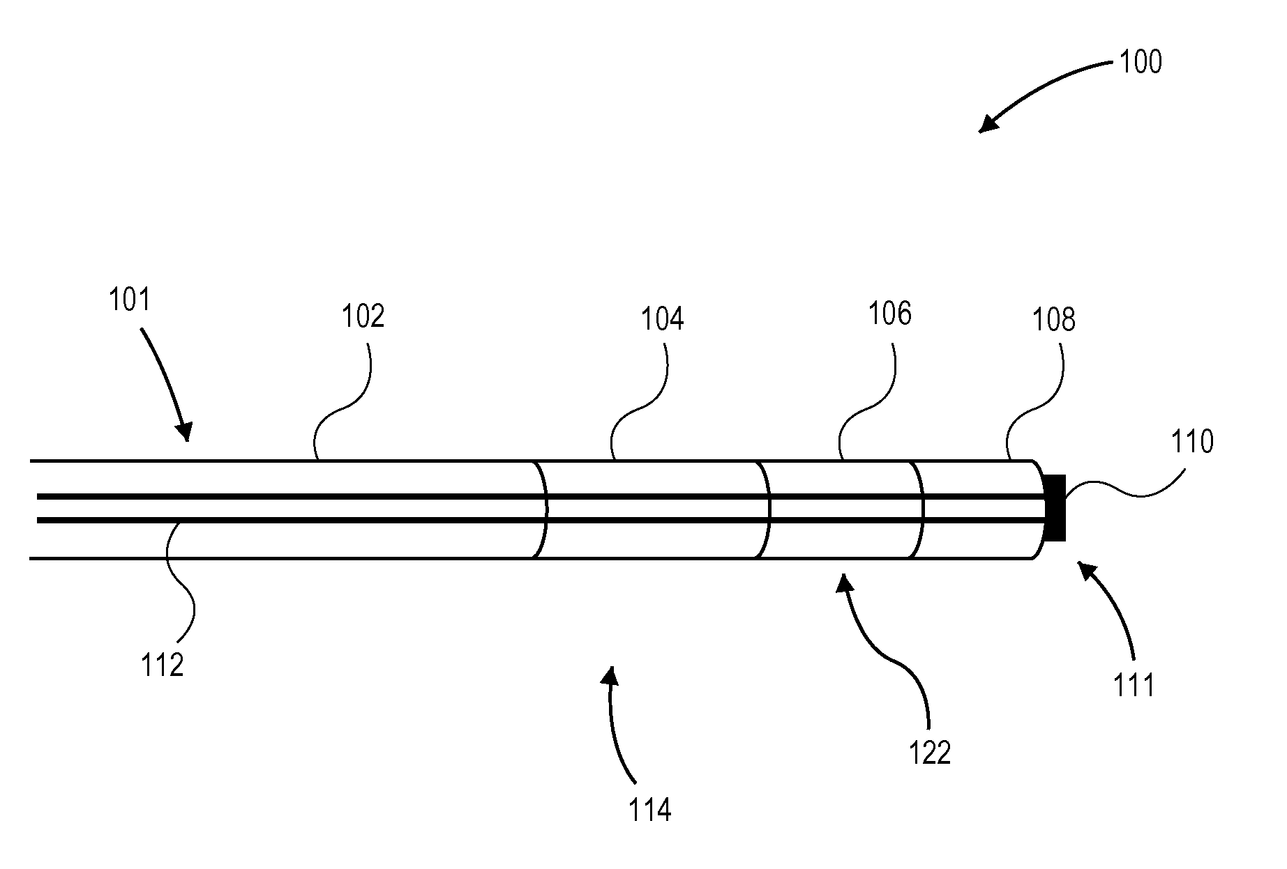
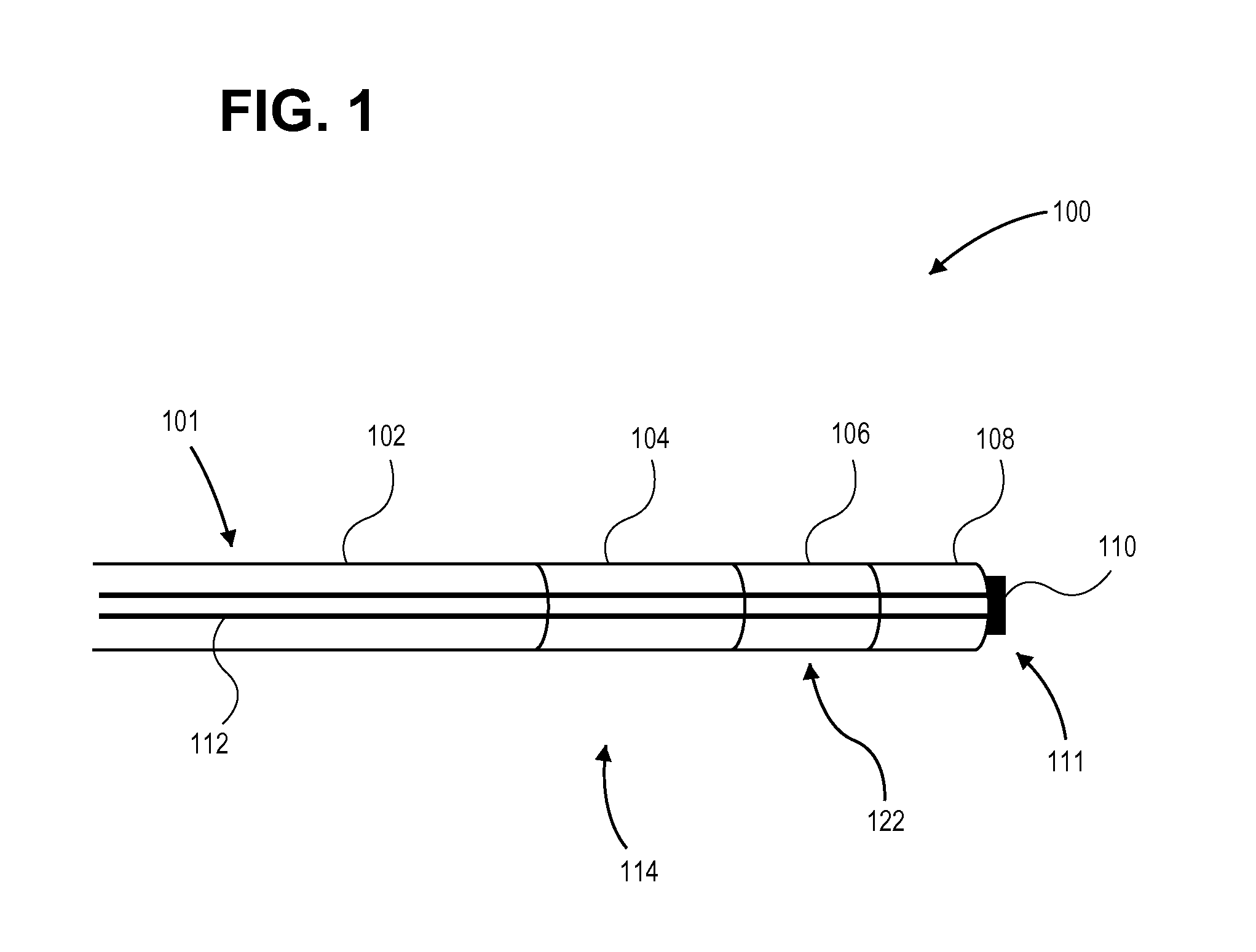
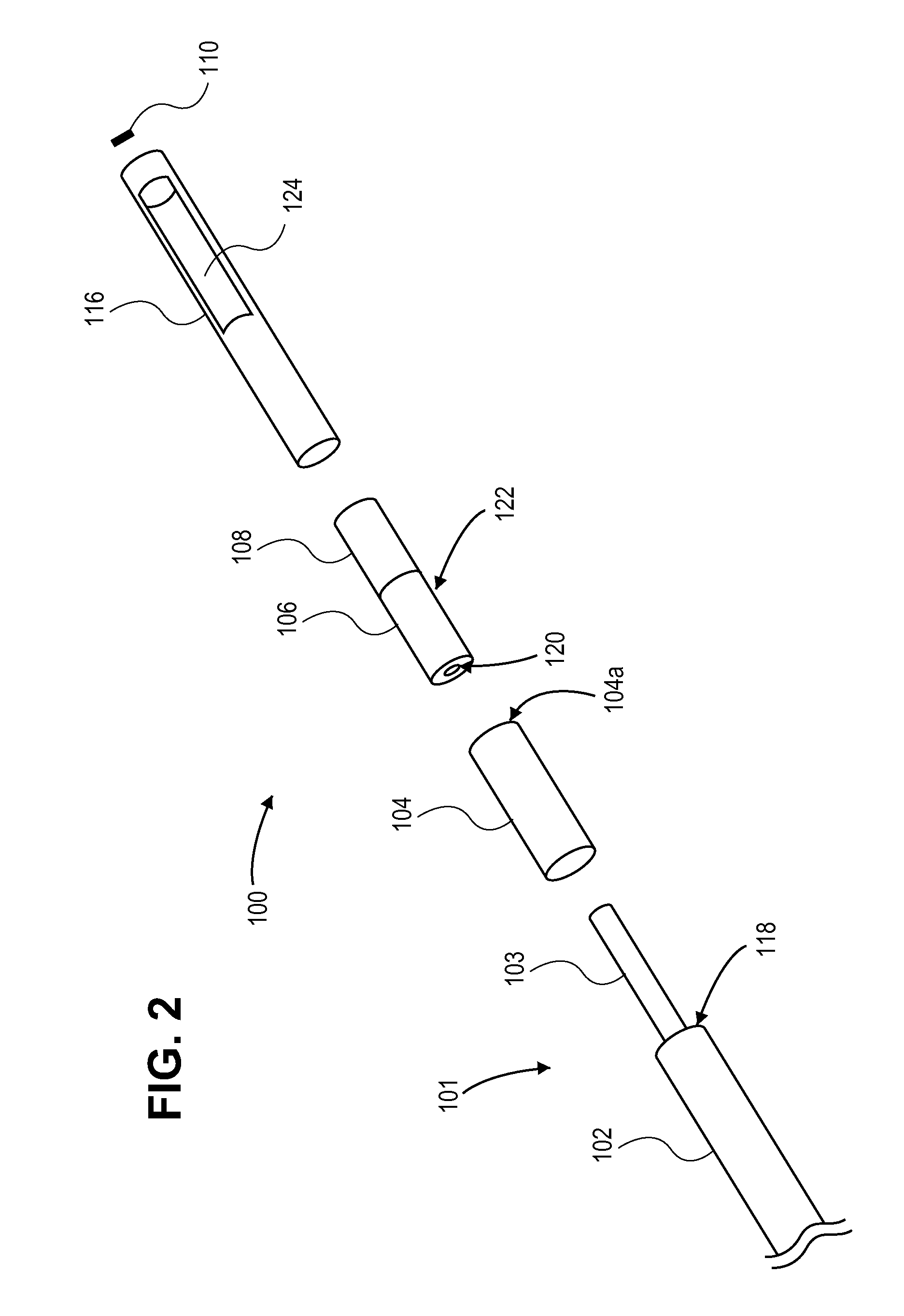
[0029]FIG. 1 is a cross-sectional illustration of a dual energy therapy needle 100 comprising coaxial cable 101, ferrule 104, dielectric element 106, electric wall 108, ...


PUM


Abstract

A therapy needle is provided that may include any of a number of features. One feature of the therapy needle is that it can apply microwave energy to tissue to produce a coagulative spherical volumetric ablation of the tissue. In some embodiments, the volumetric ablation can have a diameter ranging from 1 cm to 4 cm and can be formed in less than 3 minutes. Another feature of the therapy needle is that it can utilize an electric cutting device on a distal portion of the needle to cut a hole in high density tissue. Methods associated with use of the therapy needle are also covered.

Description

CROSS-REFERENCE TO RELATED APPLICATIONS[0001]This application claims priority under 35 U.S.C. §119 to U.S. Provisional Patent Application No. 61 / 175,882, filed May 6, 2009, which application is incorporated by reference in its entirety.INCORPORATION BY REFERENCE[0002]All publications and patent applications mentioned in this specification are herein incorporated by reference to the same extent as if each individual publication or patent application was specifically and individually indicated to be incorporated by reference.FIELD OF THE INVENTION[0003]The present application is directed to methods and apparatus that provide therapeutic treatment of internal pathological conditions using microwave energy. The present application is also directed to methods and apparatus that provide therapeutic treatment of internal pathological conditions using microwave energy and RF energy.BACKGROUND OF THE INVENTION[0004]A variety of therapeutic uses have been described to treat pathological condi...

Claims


Application Information

Patent Timeline
Patent Type & Authority Applications(United States)
IPC IPC(8): A61B18/18
CPCA61B18/1477A61B18/18A61B18/1815A61B2018/1869A61B2017/00084A61B2018/1425A61B18/24
Inventor FELDBERG, IANBEALE, GARY
Owner GYNESONICS
Learn More