Annuloplasty ring with intra-ring anchoring

Active Publication Date: 2010-11-11
VALTECH CARDIO LTD
View PDF99 Cites 199 Cited by
  • Summary
  • Abstract
  • Description
  • Claims
  • Application Information

AI Technical Summary

Benefits of technology

[0052]The annuloplasty ring is typically configured to be placed only partially around the valve annulus (i.e., to assume a C-shape), and, once anchored in place, to be contracted so as to circumferentially tighten the valve annulus. To this end, the annuloplasty ring comprises a flexible contracting member such as a wire, which is typically positioned within the lumen of the sleeve. The annuloplasty ring further comprises a contracting mechanism which facilitates contracting of the annuloplasty ring. For some applications, the contracting mechanism comprises a spool to which a first end of the contracting member is coupled. The spool is positioned in a vicinity of either the proximal or the distal end of the sleeve. A second end of the contracting member is coupled to the sleeve in a vicinity of the end of the sleeve opposite the end to which the spool is positioned. Rotation of the spool winds a portion of the contracting member around the spool, ther

Problems solved by technology

Mitral regurgitation of blood from the left ventricle into the left atrium results in increased total stroke volume and decreased ca

Method used


Image

  • Annuloplasty ring with intra-ring anchoring
  • Annuloplasty ring with intra-ring anchoring
  • Annuloplasty ring with intra-ring anchoring

Examples


Embodiment Construction

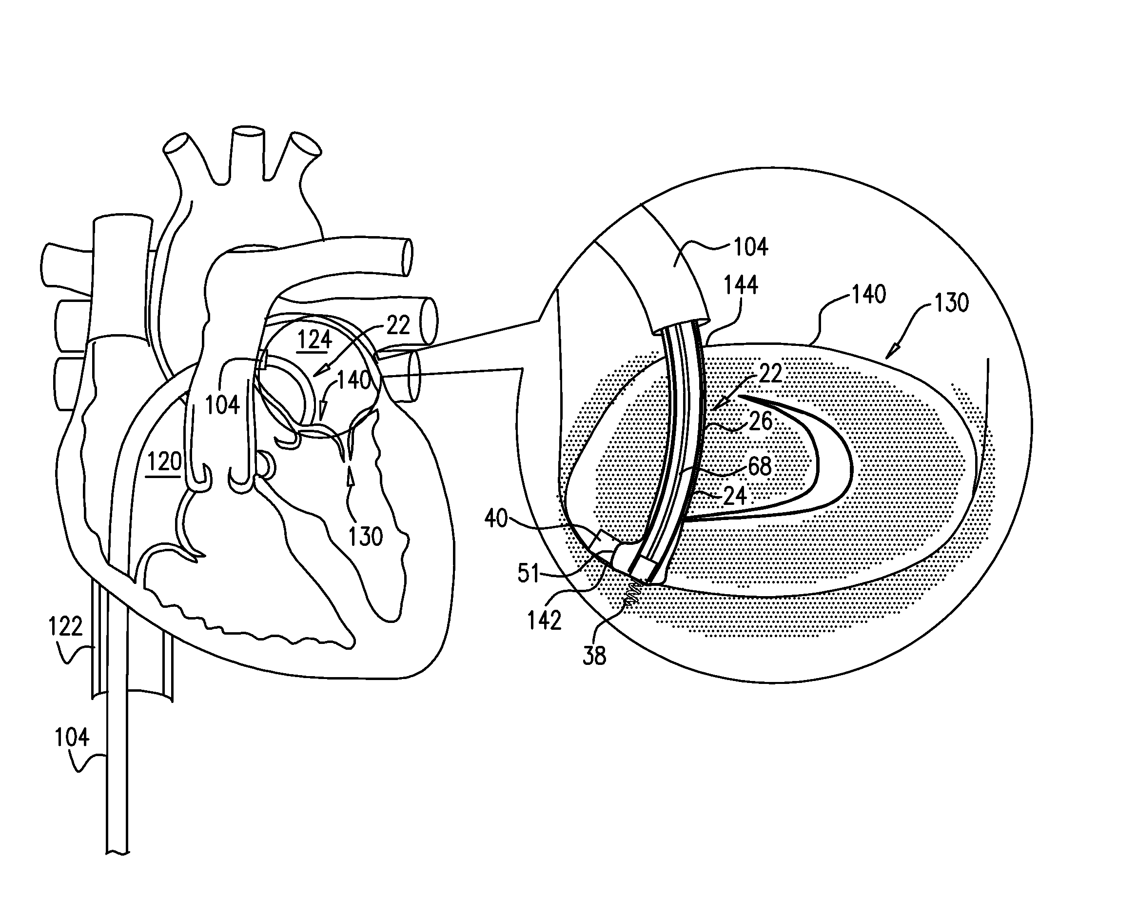
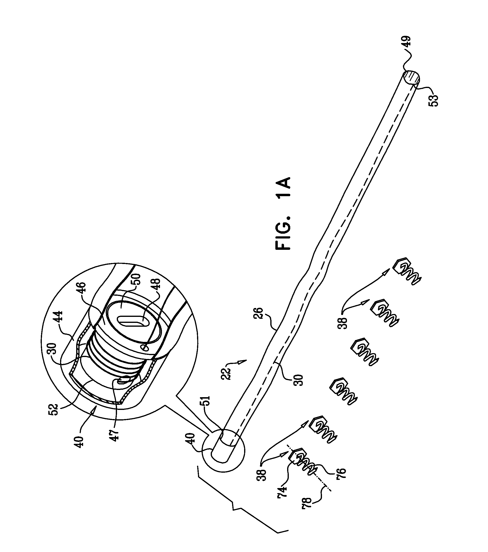
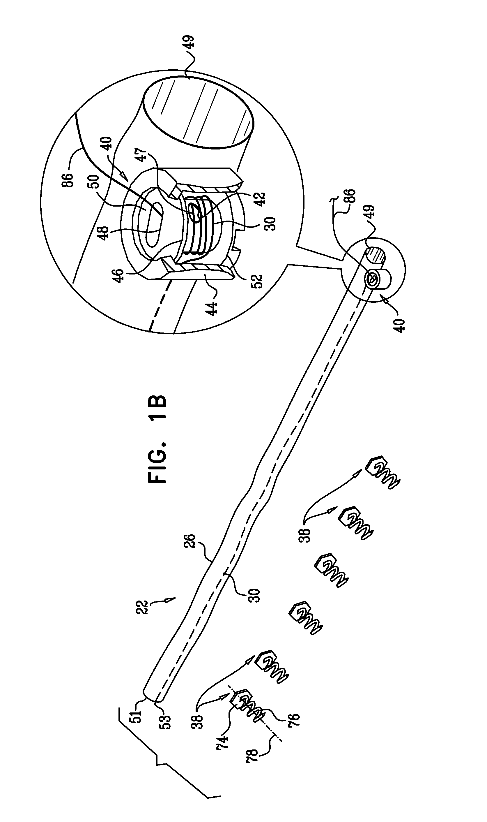
[0156]FIGS. 1-4 are schematic illustrations of a system 20 for repairing a dilated atrioventricular valve, such as a mitral valve, in accordance with an embodiment of the present invention. System 20 comprises an adjustable partial annuloplasty ring 22, shown alone in FIGS. 1A and 1B in a non-contracted state, and an anchor deployment manipulator 24, shown alone in FIG. 2. Annuloplasty ring 22 comprises a flexible sleeve 26. Anchor deployment manipulator 24 is advanced into sleeve 26, as shown in FIGS. 3 and 4, and, from within the sleeve, deploys anchors 38 through a wall of the sleeve into cardiac tissue, thereby anchoring the ring around a portion of the valve annulus.

[0157]FIGS. 1A and 1B are schematic illustration of annuloplasty ring 22 in a non-contracted state, in accordance with respective embodiments of the present invention. Sleeve 26 is typically configured to be placed only partially around the valve annulus (i.e., to assume a C-shape), and, once anchored in place, to b...


PUM


Abstract

Apparatus is provided that includes an annuloplasty system for use on a subject. The system includes an annuloplasty ring, which includes a sleeve having a lumen, and at least one anchor, shaped so as to define a coupling head and a tissue coupling element, which tissue coupling element is shaped so as to define a longitudinal axis, and is configured to penetrate cardiac tissue of the subject in a direction parallel to the longitudinal axis. The system further includes an anchor deployment manipulator, configured to be removably positioned within the lumen of the sleeve, and, while so positioned, to deploy the tissue coupling element from a distal end of the deployment manipulator through a wall of the sleeve into the cardiac tissue in the direction parallel to the longitudinal axis of the tissue coupling element and parallel to a central longitudinal axis through the distal end of the deployment manipulator.

Description

FILED OF THE INVENTION[0001]The present invention relates in general to valve repair, and more specifically to repair of an atrioventricular valve of a patient.BACKGROUND OF THE INVENTION[0002]Ischemic heart disease causes mitral regurgitation by the combination of ischemic dysfunction of the papillary muscles, and the dilatation of the left ventricle that is present in ischemic heart disease, with the subsequent displacement of the papillary muscles and the dilatation of the mitral valve annulus.[0003]Dilation of the annulus of the mitral valve prevents the valve leaflets from fully coapting when the valve is closed. Mitral regurgitation of blood from the left ventricle into the left atrium results in increased total stroke volume and decreased cardiac output, and ultimate weakening of the left ventricle secondary to a volume overload and a pressure overload of the left atrium.[0004]US Patent Application Publication 2007 / 0055206 to To et al., which is incorporated herein by referen...

Claims


Application Information

Patent Timeline
IPC IPC(8): A61F2/24
CPCA61F2/2445A61B17/064A61F2/2466A61B2017/0649A61F2/2442A61B17/068A61F2220/0016A61B17/00234A61B2017/00243A61B2017/0647
Inventor ZIPORY, YUVALCABIRI, OZGROSS
Owner VALTECH CARDIO LTD
Why Eureka
Try Eureka