
Remote-controlled fluttering object capable of flying forward in upright position

Inactive Publication Date: 2010-11-18
HANWHA CORP
View PDF8 Cites 21 Cited by
  • Summary
  • Abstract
  • Description
  • Claims
  • Application Information

AI Technical Summary

Benefits of technology

[0021]Accordingly, the present invention has been made keeping in mind the above problems occurring in the prior art, and an object of the present invention is to provide a remote-controlled ornithopter capable of flying forward in the upright position, in which two pairs of main wings are provided in an X arrangement, so that the main wings have an opposite phase difference while flapping and, therefore, the difference in pressure between space between the two pairs of main wings and space outside the main wings is increased, thus maximizing the aerodynamic lift.
[0022]Another object of the present invention is to provide a remote-controlled ornithopter capable of flying forward in the upright position in which, because the flapping of the two pairs of main wings acts like a pump, the thrust of the ornithopter can also be increased.
[0023]A further object of the present invention is to provide a remote-controlled ornithopter capable of flying forward in the upright position, in which, because the two pairs of main wings are operated in opposite phases, the moment that is applied to the fuselage can be maintained constant, so that air flow generated by the flapping can be generated more constantly and efficiently, thus making stable forward flight in the upright position, hovering flight, and low-speed flight possible.

Problems solved by technology

However, in the case of the ornithopter having one pair of main wings, it is difficult to generate sufficient aerodynamic lift and thrust to lift the weight of the ornithopter.
Even if sufficient aerodynamic lift and thrust are generated by the one pair of main wings, because the moment applied to the fuselage markedly varies depending on the position of the wings while flapping, there is a problem in that the air flow generated around the ornithopter by the flapping of the main wings is unsteady.
Therefore, forward flight in an upright position cannot be realized, because the balance of the ornithopter, which is an important factor for the forward flight in an upright position, is not maintained.
Furthermore, because the construction of the technique and a method of implementing it are complex, it is very difficult to realize the technique.
Therefore, it is impossible to conduct stable forward flight in the upright position.
However, because these remote-control methods are well-known methods that have been used for a long time, there is a disadvantage in that the sense of realism in performing remote control is reduced and a user may become easily bored, soon losing interest.
However, there are disadvantages in that the method of installing the sensor in the controller and the mechanism thereof are very complex, and the cost of materials increases due to the use of the sensor.

Method used


Image

  • Remote-controlled fluttering object capable of flying forward in upright position
  • Remote-controlled fluttering object capable of flying forward in upright position
  • Remote-controlled fluttering object capable of flying forward in upright position

Examples


Embodiment Construction

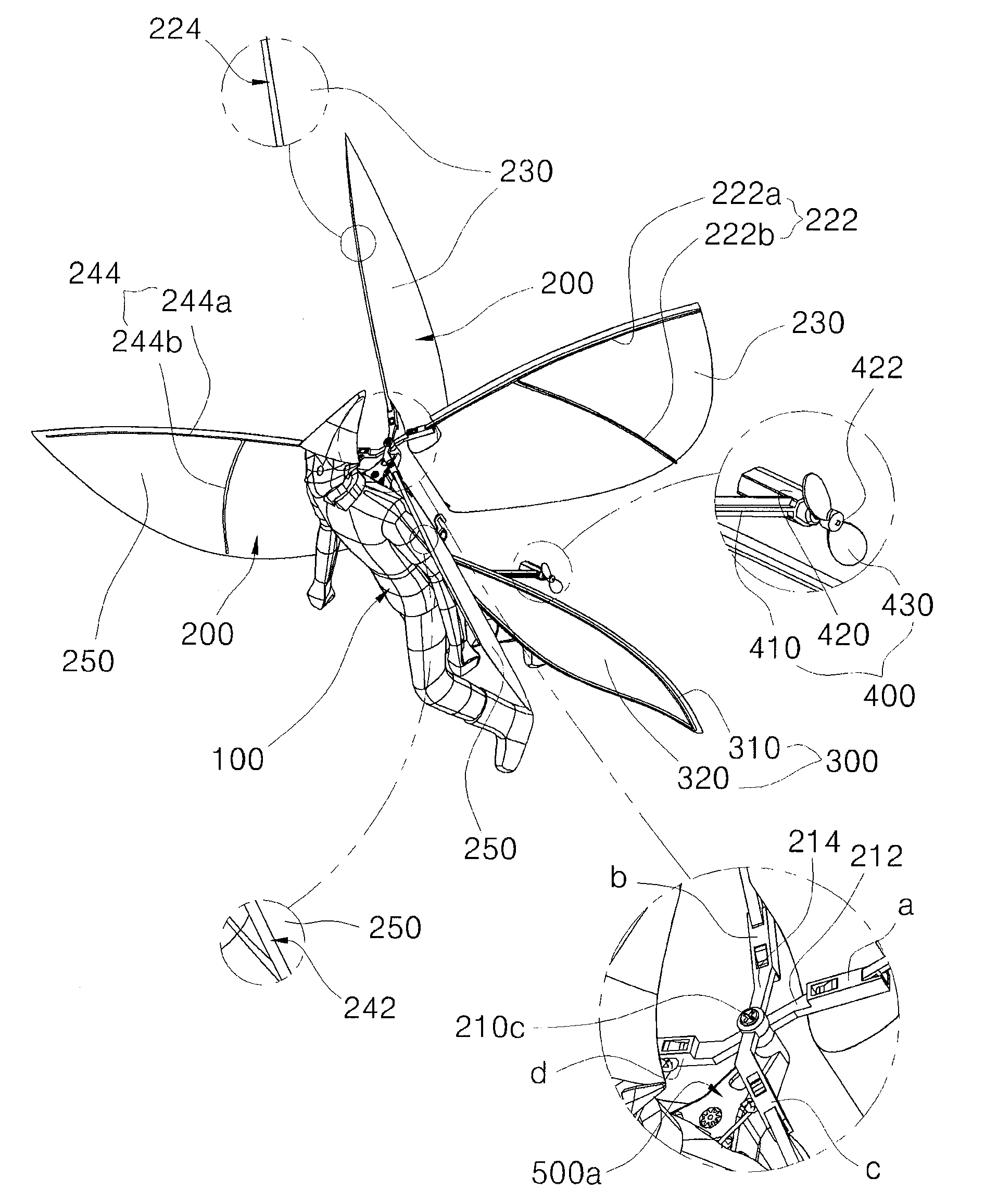
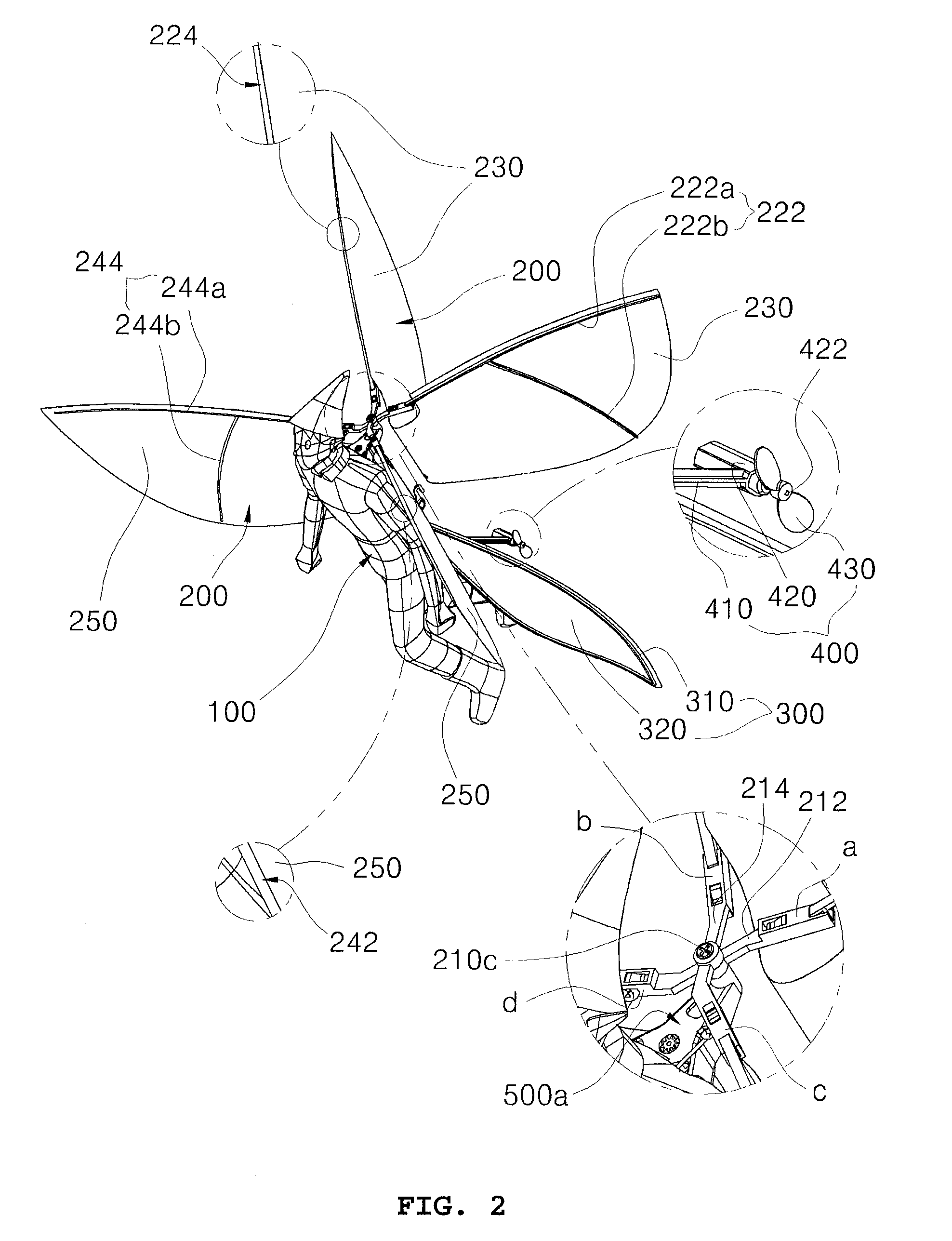
[0053]A remote-controlled ornithopter capable of flying forward in the upright position according to an embodiment of the present invention includes a fuselage 100, main wings 200, tail wings 300, a tail rotor unit 400, a drive unit 500 and a flight control unit 600.

[0054]The remote-controlled ornithopter further includes a remote controller 700, which transmits control signals for controlling the drive unit 500.

[0055]The fuselage 100 forms the entire body of the remote-controlled ornithopter. The main wings 200 are provided on the upper surface of the front end of the fuselage 100, and conduct a flapping operation. The tail wings 300 are provided on the upper surface of the medial part or the rear end of the fuselage 100, and serve to maintain horizontal balance. The tail rotor unit 400 serves to change the direction in which the fuselage 100 flies. The drive unit 500 serves to operate the main wings 200. The flight control unit 600 has a receiver 610, which receives control signal...


PUM


Abstract

The present invention provides a remote-controlled ornithopter capable of flying forward in the upright position, which includes X-shaped main wings? having opposite phases to offset moments applied to a fuselage of the ornithopter. The ornithopter includes the fuselage (100), the X-shaped main wings (200), which are provided on the front end of the fuselage, tail wings (300), which are provided on the medial portion or the rear end of the fuselage, and a tail rotor (400), which controls a direction in which the fuselage flies. The ornithopter further includes a drive unit (500), which operates the main wings, and a flight control unit (600), which has a receiver to receive a signal for controlling the drive unit and the tail rotor. The ornithopter further includes a remote controller (700), which transmits the signal for controlling the drive unit and the tail rotor to the receiver.

Description

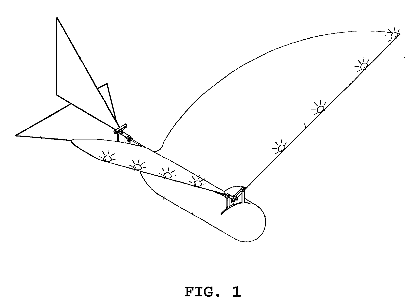
TECHNICAL FIELD[0001]The present invention relates, in general, to remote-controlled ornithopters capable of flying forward in an upright position and, more particularly, to a remote-controlled ornithopter which can fly forward in an upright position using flapping motion, like fairies in Sci-Fi movies or animations, and in which the flight thereof can be remote-controlled.BACKGROUND ART[0002]Generally, ornithopters have structures such that rotating shafts of drive motors are coupled to main wings through connecting rods and gear trains. In such an ornithopter, the main wings flaps using the rotating force of the rotating shaft of the drive motor. The ornithopter flies using aerodynamic lift generated by the flapping of the main wings.[0003]FIG. 1 is a perspective view showing a conventional ornithopter. As shown in FIG. 1, the conventional ornithopter, which was proposed in Korean Patent Laid-open Publication No. 2003-0044625, and is entitled ‘POWER-DRIVEN ORNITHOPTER PILOTED BY R...

Claims


Application Information

Patent Timeline
IPC IPC(8): B64C33/00
CPCA63H30/04A63H27/008
Inventor HWANG, HEE CHULPAIK, II HYUNKIM, JAE YEON
Owner HANWHA CORP
Learn More