Capacitive touch panel device

a touch panel and capacitive technology, applied in the direction of resistance/reactance/impedence, instruments, computing, etc., can solve the problems of reducing the processing speed and imposing a load on an external device, affecting the response time, and affecting the accuracy of the detection coordinates, so as to minimize the increase in response time

Active Publication Date: 2010-11-18
KYOCERA CORP
View PDF10 Cites 64 Cited by
  • Summary
  • Abstract
  • Description
  • Claims
  • Application Information

AI Technical Summary

Benefits of technology

[0013]An exemplary object of the present invention is to provide a capacitive touch panel device that is capable of detecting multi-touches while minimizing the increase in the response time.

Problems solved by technology

When a multi-touch capability for simultaneously detecting two or more touch points is to be implemented for use with a touch panel based on the first method, the problem of ghost points arises so that detected coordinates do not always agree with actually touched points.
Further, if any process needs to be performed by external firmware, another problem occurs to decrease the speed of processing and impose a load on an external device.
This causes a problem where the size and shape of applicable touch panels are limited or the scan rate is lower than when the first method is used.
It means that the use of the second method increases the response time.

Method used


Image

  • Capacitive touch panel device
  • Capacitive touch panel device
  • Capacitive touch panel device

Examples


Embodiment Construction

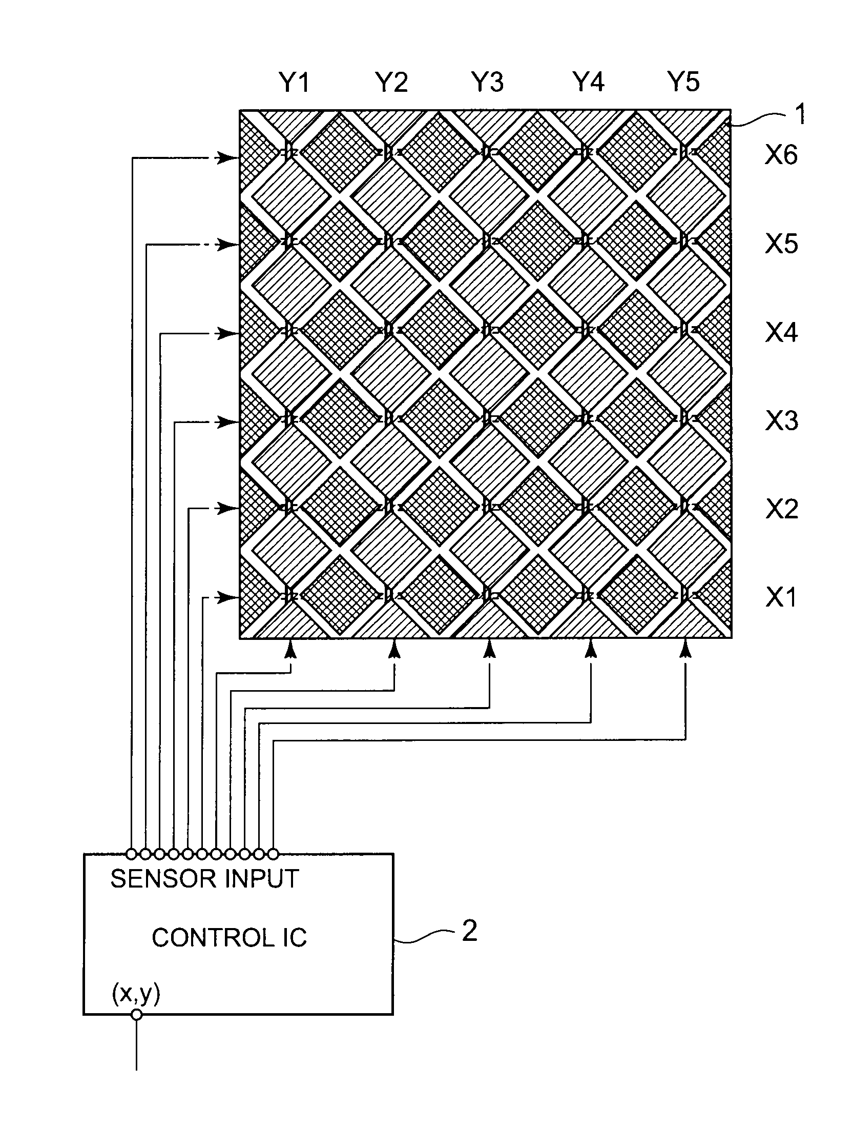
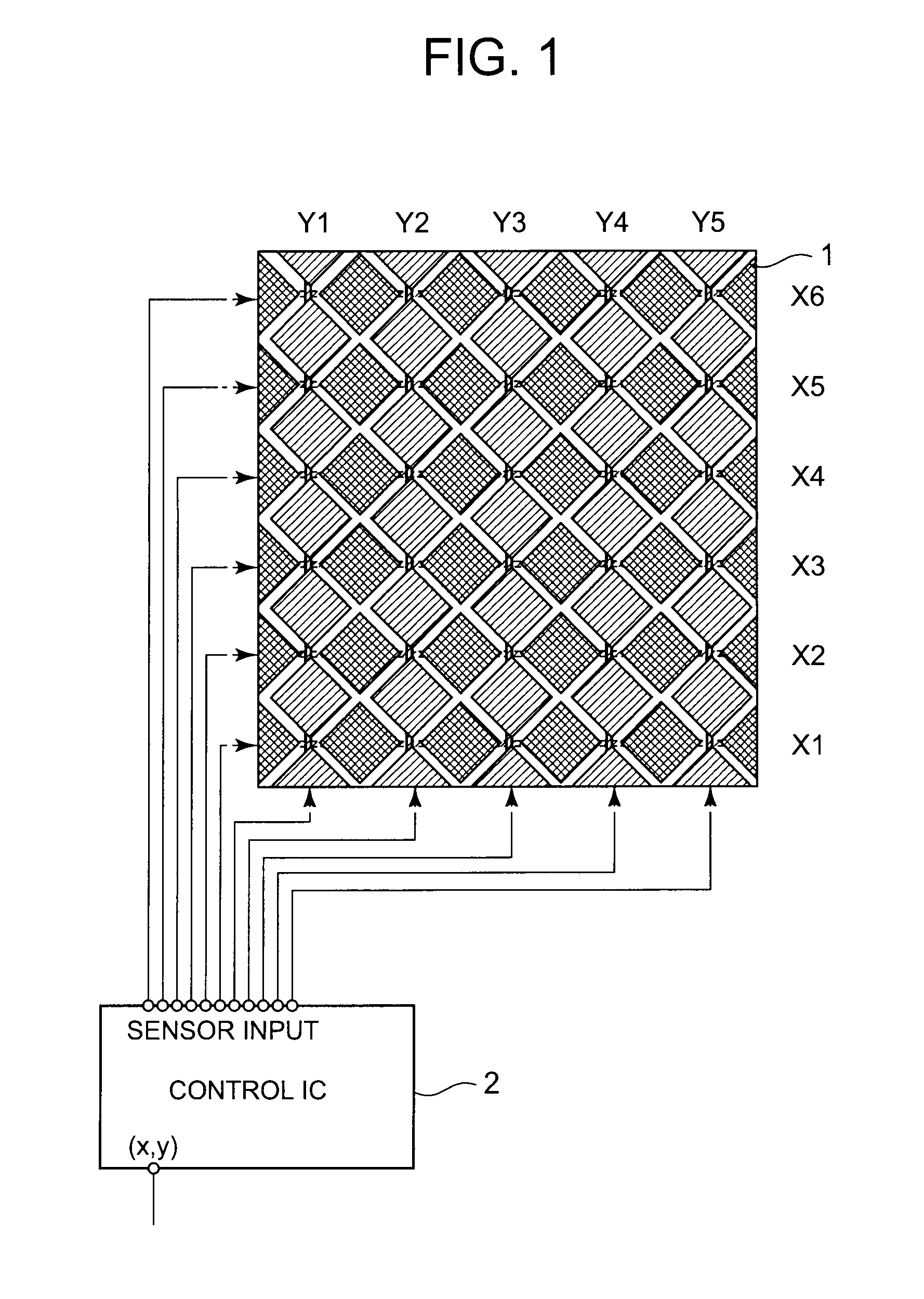
[0055]An exemplary embodiment of the present invention will now be described with reference to the accompanying drawings. FIG. 1 is a diagram illustrating an example of a capacitive touch panel device according to the present invention. As shown in FIG. 1, the capacitive touch panel device includes a capacitive touch panel 1 and a control IC 2, which drives the touch panel 1.

[0056]The touch panel 1 is placed on a transparent substrate made, for instance, of glass or PET film in such a manner that ITO or other transparent electrodes do not overlap with each other. Areas in which sensor lines X1 to X6 extended in the x direction intersect sensor lines Y1 to Y5 extended in the y direction, which is different from the x direction, are provided, for instance, with an insulating layer (not shown) so that there is no conduction between the X1 to X6 sensor lines and Y1 to Y5 sensor lines. It is preferred that the areas of the intersections of the sensor lines be minimized.

[0057]FIG. 1 shows...


PUM


Abstract

Disclosed is a capacitive touch panel device having a sensing control unit that performs a scan sequence on individual sensor electrodes to measure sensor output values. The sensing control unit exercises control to measure sensor output values, with setup performed to avoid the detection of sensitivity slope, by executing a first scan sequence on all sensor electrodes. If the result of the first scan sequence indicates that multiple points are touched, the sensing control unit exercises control to measure sensor output values again, with setup performed to allow the detection of sensitivity slope, by executing a second scan sequence on the sensor electrodes related to a plurality of touch position candidate coordinates derived from multiple point touches, and identify and eliminate erroneously detected coordinates in accordance with the sensor output values measured upon the execution of the second scan sequence and with the tendency of sensitivity slope.

Description

[0001]This application is based upon and claims the benefit of priority from Japanese Patent Application No. 2009-118060, filed on May 14, 2009, the disclosure of which is incorporated herein in its entirety by reference.TECHNICAL FIELD[0002]The present invention relates to a capacitive touch panel device.BACKGROUND ART[0003]There is a sensing method for use with a capacitive touch panel. This method uses each of a plurality of sensor electrodes patterned with ITO (Indium Tin Oxide) or other transparent electrodes as an independent sensor to capture and quantify capacitance changes. This method may be called a self-capacitance method or a single sensor method. Here, this method is referred to as a first method.[0004]There is another sensing method for use with a capacitive touch panel. The functionality of this method is divided into two categories for quantification purposes: driving side and sensing side. The driving side charges and discharges capacitance generated between electr...

Claims


Application Information

Patent Timeline
Patent Type & Authority Applications(United States)
IPC IPC(8): G06F3/045
CPCG06F3/0418G06F2203/04111G06F2203/04104G06F3/044G06F3/04186G06F3/0446
Inventor WATANABE, KIYOSHI
Owner KYOCERA CORP
Why Eureka
Try Eureka