
Method and image-processing device for hole filling

a technology of image processing and hole filling, which is applied in the field of method and image processing device, can solve the problems of insufficiently addressed problems, inability to provide input data for certain output pixels, and inability to identify the source area of the hole, so as to prevent the propagation of inappropriate pixel values, and improve the confidence

Inactive Publication Date: 2010-11-18
KONINKLIJKE PHILIPS ELECTRONICS NV
View PDF7 Cites 6 Cited by
  • Summary
  • Abstract
  • Description
  • Claims
  • Application Information

AI Technical Summary

Benefits of technology

[0009]This object is achieved by a method of assigning pixel values to adjacent pixel locations in an image having unassigned pixel values, the method comprising the steps of: generating first propagation pixel values and first propagation weights for propagating the first propagation pixel values along a first direction towards the adjacent pixel locations by: generating the first propagation pixel values for propagation to the adjacent pixel locations in the first direction, the first propagation pixel values being based at least on assigned pixel values in a first region adjacent to the unassigned pixel locations; generating first propagation weights for the first propagation pixel values to account for discontinuities in pixel values of assigned pixel values in a second region adjacent to the hole along the first direction, such that the occurrence of a discontinuity in said assigned pixel values along the first direction results in lower first propagation weights; and assigning pixel values to the adjacent pixel locations based at least in part on the first propagation pixel values and first propagation weights.
[0011]The weights are based on assigned pixel values from the second region along the first direction. When a strong discontinuity in pixel values “crosses” the hole, the weight associated with pixel locations before the “crossing” (as perceived when moving along the first direction) will have a higher confidence than the pixel locations past the “crossing”. In this manner, the present invention prevents erroneous propagation of inappropriate pixel values.
[0013]In one embodiment, the first propagation pixel values are generated by means of a first directional filter over assigned pixel values comprising pixel locations with assigned pixel values in the first region adjacent to the unassigned pixel locations. In this manner, the first propagation values can be made more robust to noise, as multiple pixels are used. Moreover, as occlusion and de-occlusion is generally a gradual process, filtering of multiple pixels per frame further provides additional time consistency, as the first propagation values are not dependent on the pixel locations in the first region directly adjacent to the hole only.
[0016]In yet another embodiment, the step of assigning pixel values to the adjacent pixel locations comprises blending the first propagation pixel values weighted with the first propagation weights with the second propagation pixel values weighted with the second propagation weights. In this manner, a simple implementation that does not require demanding processing steps is obtained.

Problems solved by technology

When transforming images in the image+depth video format to a plurality of images viewed from different positions, it may occur that no input data is available for certain output pixels.
Furthermore, unreferenced areas causing holes may be present in the background in object-based video-encoding schemes, e.g. MPEG-4, in which backgrounds and foregrounds are encoded separately.
Although the above solution provides a distinct improvement that reduces visual distortion, there are still issues that are not fully addressed by the above solution.

Method used


Image

  • Method and image-processing device for hole filling
  • Method and image-processing device for hole filling
  • Method and image-processing device for hole filling

Examples


Embodiment Construction

[0039]Several applications that address the concept of hole filling are known in the world of image processing. Two of such applications have already been indicated hereinbefore, viz. filling in de-occluded areas in images for view rendering based on video information provided in the image+depth video format, and prediction of information in shift motion prediction in video compression schemes. Further alternative application areas are e.g. image restoration.

[0040]Several approaches are known to address hole filling in different manners. Such an approach is disclosed in International Patent Application WO2007 / 099465. However, these techniques generally have the drawback that they lead to a temporally stable solution. Certain embodiments of the present invention, in particular those involving blending of multiple propagation pixel values, provide a computationally simple, yet temporally stable hole-filling solution.

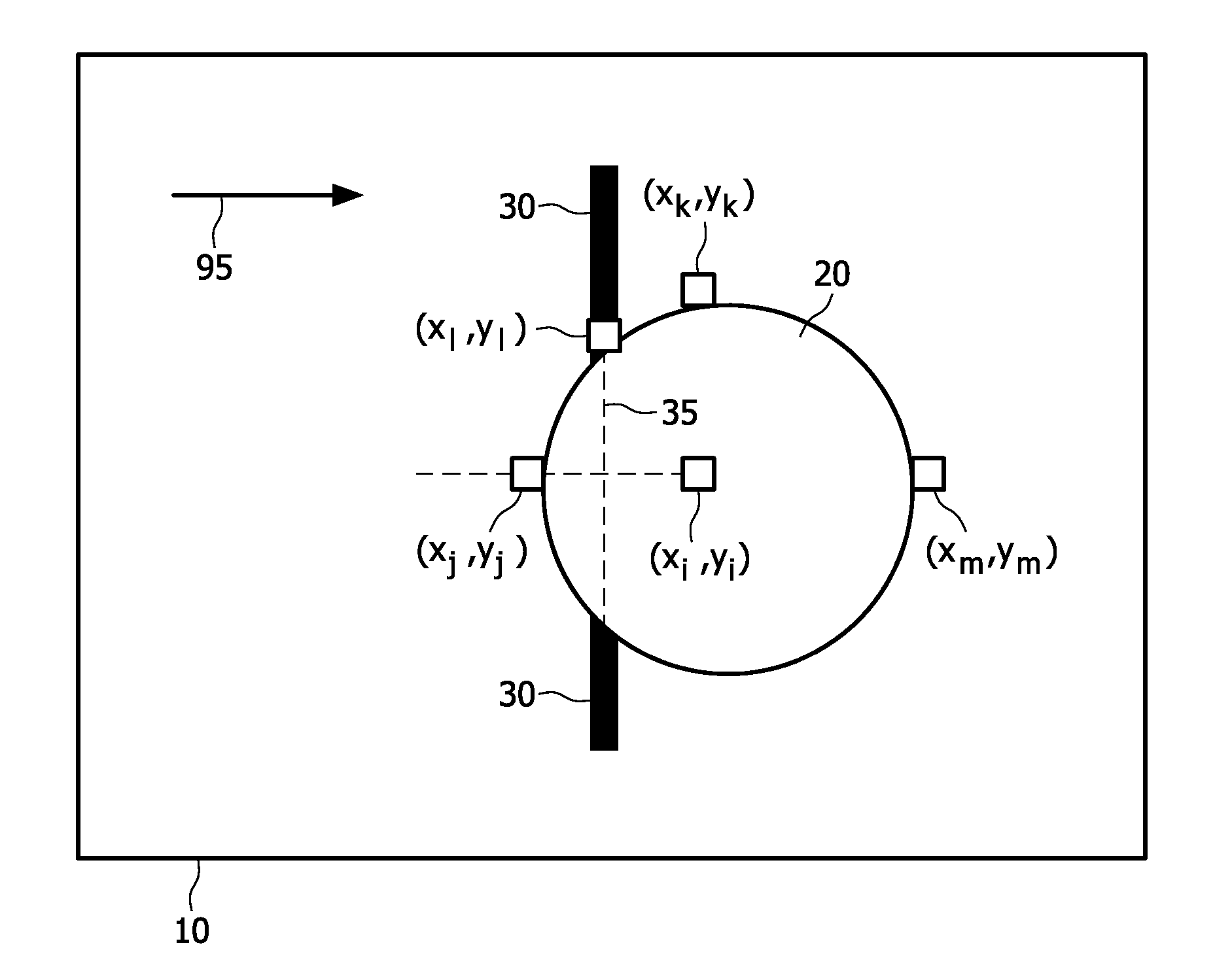
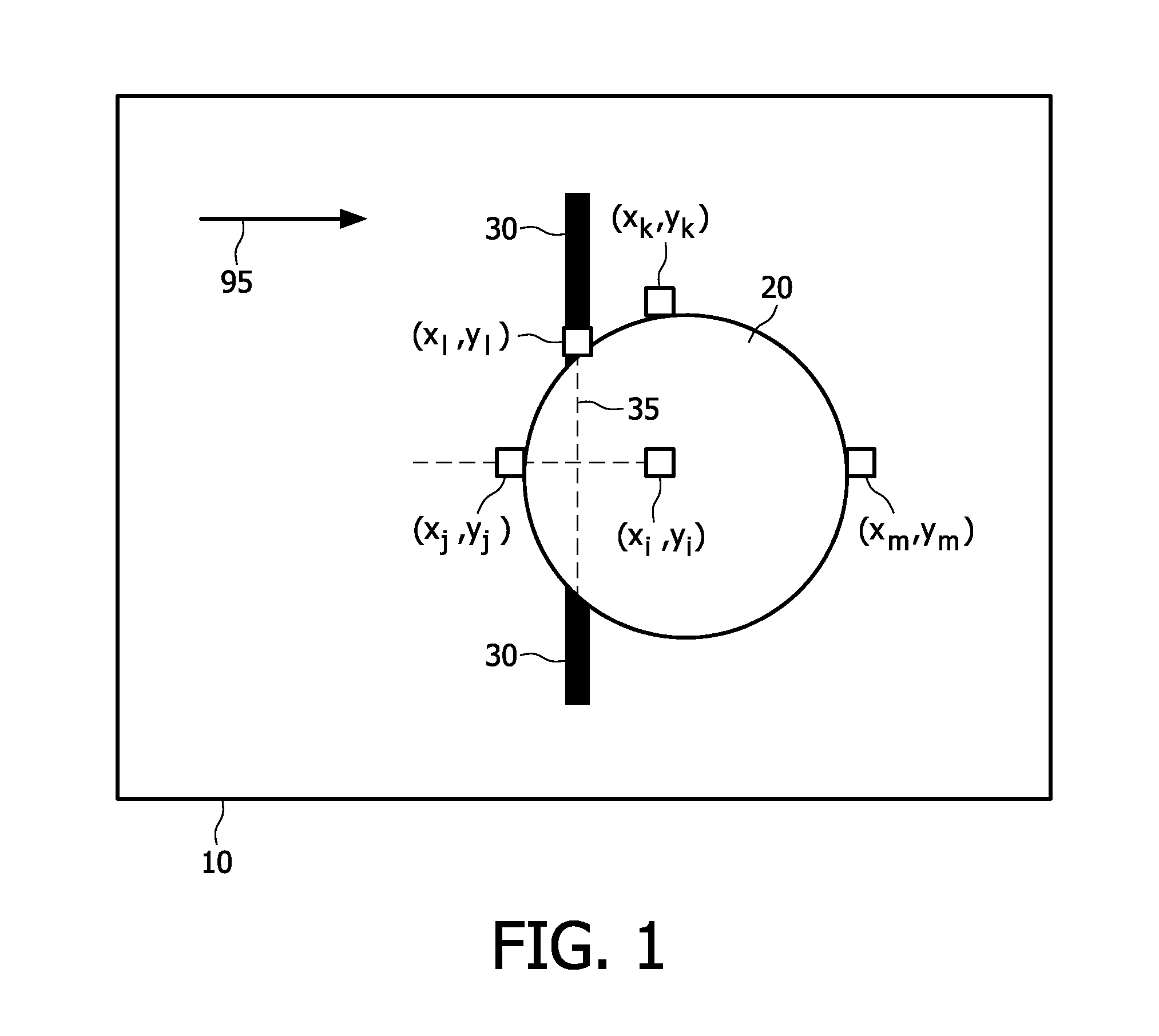
[0041]FIG. 1 shows a hole-filling method according to the present inv...


PUM


Abstract

The present invention relates to an image-processing device and a method of assigning pixel values to adjacent pixel locations in an image (705) having unassigned pixel values. The method comprises the steps of generating first propagation pixel values (730) and first propagation weights (735) for propagating the first propagation pixel values (730) along a first direction towards the adjacent pixel locations by: generating the first propagation pixel values (730) for propagation to the adjacent pixel locations in the first direction, the first propagation pixel values (730) being based at least on assigned pixel values in a first region adjacent to the unassigned pixel locations; generating first propagation weights (735) for the first propagation pixel values (730) to account for discontinuities in pixel values of assigned pixel values in a second region adjacent to the hole along the first direction, such that the occurrence of a discontinuity in said assigned pixel values along the first direction results in lower first propagation weights (735); and assigning pixel values to the adjacent pixel locations based at least in part on the first propagation pixel values (730) and first propagation weights (735). The invention further relates to a computer program and a computer program product comprising the program for implementing the method.

Description

FIELD OF THE INVENTION[0001]The present invention relates to a method and image-processing device for assigning pixel values to adjacent pixel locations in an image having unassigned pixel values, as well as to a computer program and a computer program product for causing the method to be executed when said computer program is run on a computer.BACKGROUND OF THE INVENTION[0002]Currently, the Consumer Electronics industry is increasingly interested in giving consumers a three-dimensional image / video experience at home. A growing number of displays is becoming available to the general public. These displays include glass-based stereoscopic systems presenting the user with two views, and autostereoscopic systems such as barrier and / or lenticular-based autostereoscopic displays.[0003]Both stereoscopic and autostereoscopic systems utilize the fact that it is possible to provide a perception of depth by presenting at least two images of one and the same scene, viewed from two, slightly sp...

Claims


Application Information

Patent Timeline
Patent Type & Authority Applications(United States)
IPC IPC(8): G09G5/00G06K9/40
CPCG06T2207/10016G06T5/005G06T2207/20192G06T5/77
Inventor VAREKAMP, CHRISTIAANKLEIN GUNNEWIEK, REINIER BERNARDUS MARIA
Owner KONINKLIJKE PHILIPS ELECTRONICS NV
Learn More