Illumination apparatus

a technology of illumination apparatus and illumination lamp, which is applied in the direction of lighting and heating apparatus, instruments, display means, etc., can solve the problems of low luminance efficiency of halogen bulbs, large heat, and high power consumption, and achieve the effect of reducing glar

Inactive Publication Date: 2010-11-18
CORETRONIC
View PDF14 Cites 23 Cited by
  • Summary
  • Abstract
  • Description
  • Claims
  • Application Information

AI Technical Summary

Benefits of technology

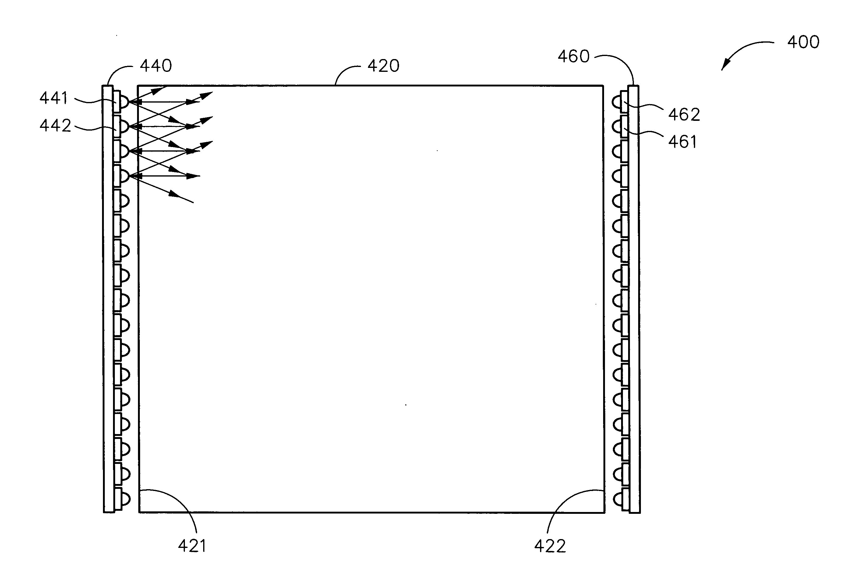
[0015]Accordingly, the invention is to provide a thin indoor illumination apparatus having function of adjusting color temperature and brightness, and capable of providing uniform plane light for reducing glare.

Problems solved by technology

The halogen bulb has a low luminance efficiency, for the halogen bulb is transparent and small, so the halogen bulb is often used in decorative art lamps.
The above two bulbs both suffer from large heat, high power consumption, low luminance efficiency, and short life.
The energy-saving bulb easily makes people feel dazzled and uncomfortable.
However, in such a way, the light beam from the point light sources forms light point easily but is hard to provide uniform plane light.
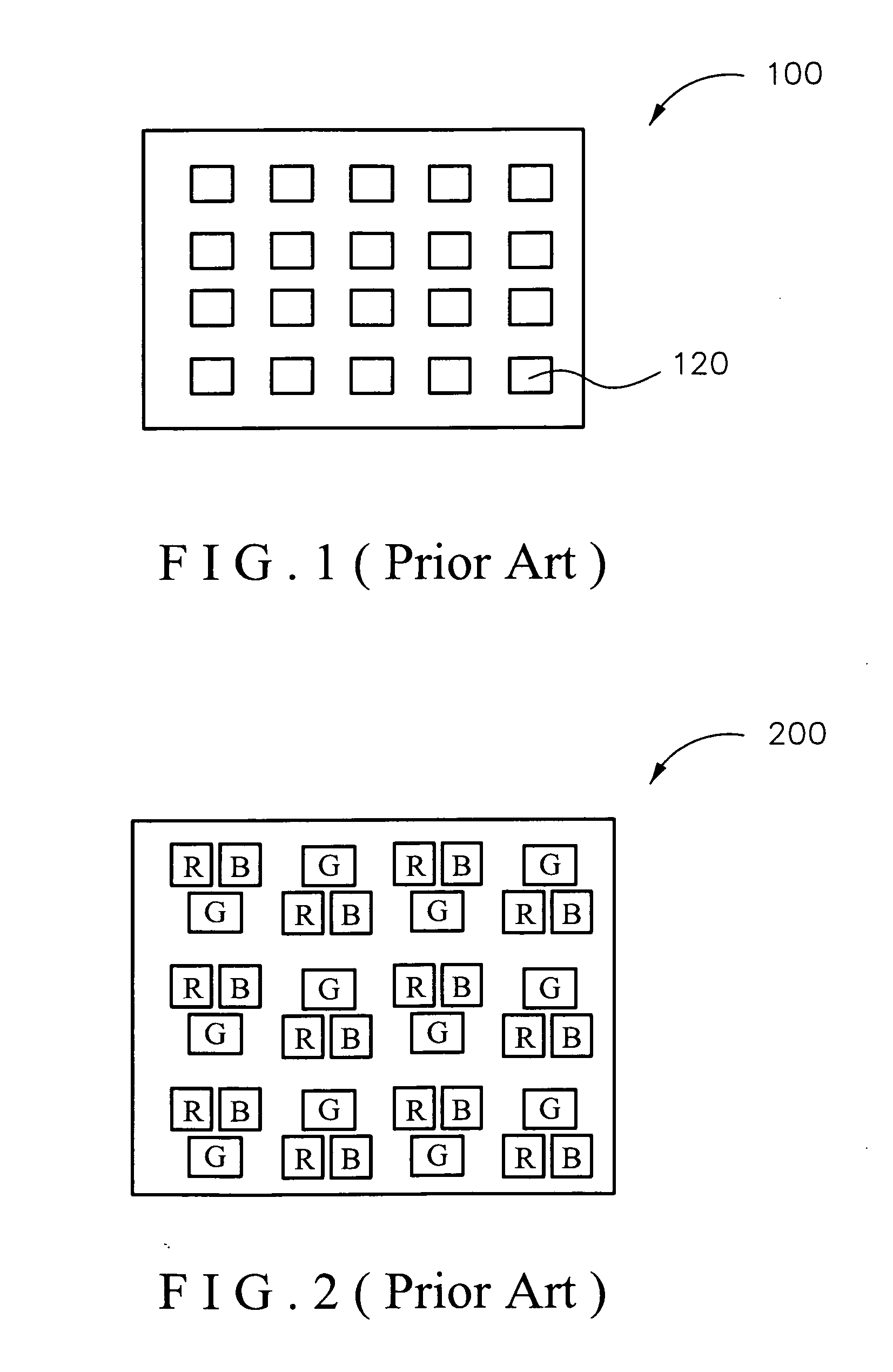
Though the illumination apparatus having red LED, green LED, and blue LED arrays may be adjusted color light from warm white to cold white, this technology currently is applied in small LED lamp to provide color change with lower brightness and also suffers from lower efficiency of mixing light and poor power saving property.
However, the light beam from the point light source forms light point easily, and a uniform plane light is hard to be provided.
Thus if the light beam enters human's eyes, glare is generated easily to make image vague and eyes tired, and the reading efficiency may be decreased.
Thus, if LED in the illumination apparatus is fixed to the PCB in the form of chip, there may be still many errors in the follow-up process, and the color appearance of the LED may be affected.

Method used


Image

  • Illumination apparatus
  • Illumination apparatus
  • Illumination apparatus

Examples


Embodiment Construction

[0031]In the following detailed description of the preferred embodiments, reference is made to the accompanying drawings which form a part hereof, and in which is shown by way of illustration specific embodiments in which the invention may be practiced. In this regard, directional terminology, such as “top,”“bottom,”“front,”“back,” etc., is used with reference to the orientation of the Figure(s) being described. The components of the present invention can be positioned in a number of different orientations. As such, the directional terminology is used for purposes of illustration and is in no way limiting. On the other hand, the drawings are only schematic and the sizes of components may be exaggerated for clarity. It is to be understood that other embodiments may be utilized and structural changes may be made without departing from the scope of the present invention. Also, it is to be understood that the phraseology and terminology used herein are for the purpose of description and...


PUM


Abstract

An illumination apparatus includes a light guide plate, a first light source module, and a second light source module. The light guide plate has a first incident surface and a second incident surface opposite to the first incident surface. The first and the second light source modules provide light beams into the first and the second incident surfaces, respectively. The first light source module includes at least one first white light emitting diode (LED) and at least one second white LED neighboring with each other. The first and the second white LEDs have different color temperatures. The second light source module includes at least one third white LED and at least one forth white LED neighboring with each other. The third and the forth white LEDs have different color temperatures. The third and the forth white LEDs are located corresponding to the second and the first white LEDs, respectively.

Description

BACKGROUND OF THE INVENTION[0001](1) Field of the Invention[0002]The present invention relates to an illumination apparatus, particularly to an indoor illumination apparatus using white light emitting diodes as light source.[0003](2) Description of the Prior Art[0004]Indoor illumination technology is widely used in office, living room, study room or bedroom for ceiling lamp or wall lamp. The indoor illumination apparatus needs non-directional and uniform light beam with a large angle to provide different brightness and color temperatures according to time and space. For example, when working in office, we need cold white light to increase attention; when dining in a rest place, we need soft warm white light to relax.[0005]There are three types of light sources in the traditional indoor illumination apparatus: fluorescent lamp, halogen bulb, and energy-saving bulb. The fluorescent lamp emits uniform light and is usually used in main indoor space. The color temperature of the fluoresc...

Claims


Application Information

Patent Timeline
Patent Type & Authority Applications(United States)
IPC IPC(8): F21V7/04
CPCH05B37/02H05B47/10
Inventor WANG, WEI-CHIHYANG, WEI-CHUNTSENG, CHI-MING
Owner CORETRONIC
Why Eureka
Try Eureka