Mobile communication system, mobile station apparatus, base station apparatus and random access channel transmitting method

a mobile communication system and random access channel technology, applied in wireless communication services, electrical equipment, wireless communication services, etc., can solve the problems of poor reception quality of downlink and large interference amount of uplink intercells to peripheral cells (cell b), and achieve the effect of increasing the amount of information notified and improving the delivery probability of random access channels

Active Publication Date: 2010-11-18
SHARP KK
View PDF11 Cites 68 Cited by
  • Summary
  • Abstract
  • Description
  • Claims
  • Application Information

AI Technical Summary

Benefits of technology

[0087]According to the present invention, it is possible to improve the delivery probability of a r

Problems solved by technology

However, a collision occurs in the case that a plurality of mobile station selects the same RACH preamble at the same transmission timing, and in this case, retransmission processing is performed.
Meanwhile, since UE_B is l

Method used


Image

  • Mobile communication system, mobile station apparatus, base station apparatus and random access channel transmitting method
  • Mobile communication system, mobile station apparatus, base station apparatus and random access channel transmitting method
  • Mobile communication system, mobile station apparatus, base station apparatus and random access channel transmitting method

Examples


embodiment 1

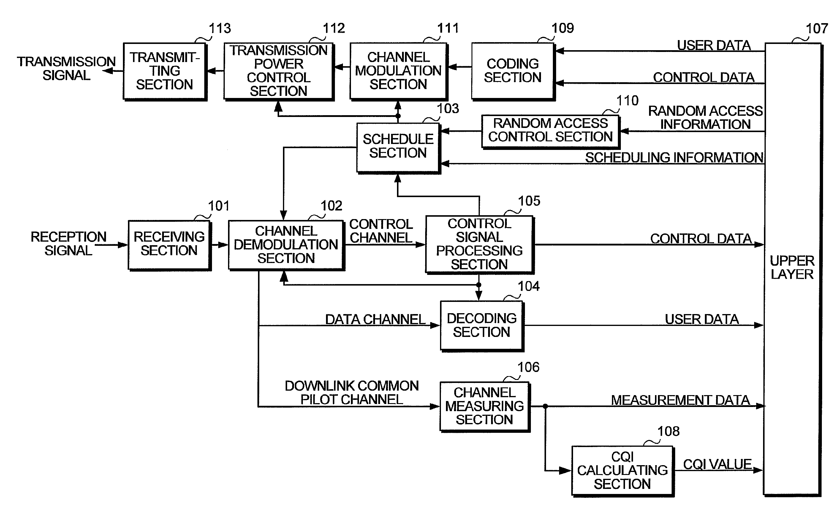
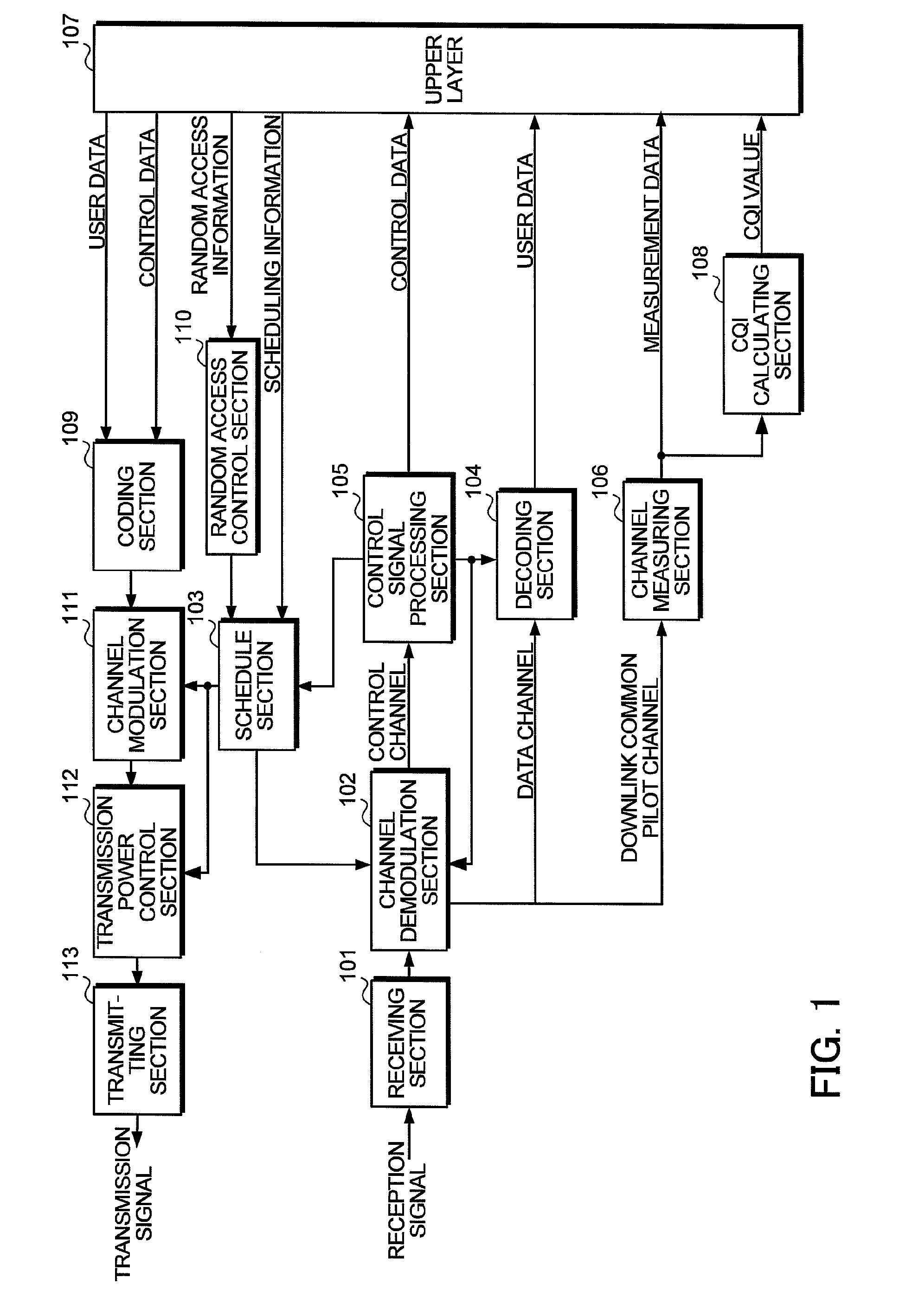
[0124]FIG. 1 is a block diagram showing an example of a configuration of a mobile station apparatus (hereinafter, referred to as a “mobile station”) included in a mobile communication system (hereinafter, referred to as a “communication system” as appropriate) according to Embodiment 1 of the present invention. In the mobile station as shown in FIG. 1, a receiving section 101 receives a reception signal. The reception signal received in the receiving section 101 is output to a channel demodulation section 102, demodulated based on scheduling information input from a schedule section 103, and classified into a data channel, control channel, and downlink common pilot channel (DL-CPICH). With respect to each classified data, the data channel is sent to a decoding section 104, the control channel is sent to a control signal processing section 105, and the downlink common pilot channel is sent to a channel measuring section 106. The decoding section 104 extracts user data to send to an u...

embodiment 2

[0167]In the communication system according to Embodiment 1, when the frequency bandwidth of the base station is a relatively narrow bandwidth such as, for example, 1.25 MHz and 2.5 MHz, and is not sufficiently wide as compared with the transmission bandwidth of the RACH, there is the possibility that required information cannot be notified to the base station. Therefore, in a communication system according to Embodiment 2, the information is implicitly notified to the base station with the transmission power of the RACH in the mobile station, in other words, the reception power (reception quality) of the RACH in the base station. In addition, configurations of the mobile station and base station constituting the communication system according to Embodiment 2 are the same as those in the communication system according to Embodiment 1, and descriptions thereof are omitted.

[0168]FIG. 12 is a diagram to explain uplink frequency regions used in RACH transmission, and transmission power ...


PUM


Abstract

To improve the delivery probability of a random access channel and increase the information amount notified on the random access channel. In a mobile communication system in which a mobile station apparatus and base station apparatus perform multicarrier communication with each other, the mobile station apparatus sets transmission control information about a random access channel based on a state of the mobile station apparatus in transmitting the random access channel, and the base station apparatus determines the state of the mobile station apparatus based on the transmission control information notified on the random access channel, and performs optimal scheduling corresponding to the state of the mobile station apparatus.

Description

TECHNICAL FIELD[0001]The present invention relates to a mobile communication system, mobile station apparatus, base station apparatus and random access channel transmitting method using a cellular wireless system.BACKGROUND ART[0002]Currently, as RAT that is Radio Access Technology, W-CDMA (Wideband-Code Division Multiple Access) specified in 3GPP (3rd Generation Partnership Project) is standardized as the 3rd generation cellular mobile communication system, and its services have been started sequentially (for example, see Non-patent Document 1).[0003]Further, evolution has been studied in 3rd Generation RAT (Evolved Universal Terrestrial Radio Access, hereinafter referred to as “EUTRA”) and 3rd Generation RAT access network (Evolved Universal Terrestrial Radio Access Network, hereinafter referred to as “EUTRAN”). In EUTRA, as a communication system, an OFDMA (Orthogonal Frequency Division Multiplexing Access) system has been proposed (for example, see Non-patent Document 2).[0004]I...

Claims


Application Information

Patent Timeline
IPC IPC(8): H04W72/12H04W74/08
CPCH04W74/0866H04B7/26H04W72/12
Inventor UEMURA, KATSUNARI
Owner SHARP KK
Why Eureka
Try Eureka