Thermal transfer sheet and ink ribbon

a transfer sheet and ink ribbon technology, applied in thermography, printing, duplicating/marking methods, etc., can solve the problems of deterioration of image quality of the ink image covered with the protective laminate, etc., to prevent the surface roughness of the transferred protective layer, good image quality, excellent image quality

Inactive Publication Date: 2010-11-18
SONY CORP
View PDF4 Cites 10 Cited by
  • Summary
  • Abstract
  • Description
  • Claims
  • Application Information

AI Technical Summary

Benefits of technology

[0008]It is desirable to provide a thermal transfer sheet and an ink ribbon each including a protective layer containing fine particles so that excellent solvent resistance and durability can be imparted to prints having ink images formed thereon, and excellent image quality can be achieved by improving detachability of the protective layer.
[0011]In the thermal transfer sheet and the ink ribbon having the above-described configurations, the particle diameter of the fine particles contained in the protective layer is defined to be 0.9 to 2.8 times the thickness of the protective layer, and thus detachability of the protective layer from the sheet base material side is secured, and surface roughness of the transferred protective layer is prevented. Therefore, as described below in examples, it was confirmed that good image quality is obtained.
[0012]As described above, a thermal transfer sheet according to an embodiment of the present invention includes a protective layer containing fine particles so that when the protective layer is transferred on a print in which an ink image is formed, excellent image quality may be achieved while imparting excellent solvent resistance and durability to the print.

Problems solved by technology

However, when the thickness of the protective layer of the thermal transfer sheet with the above-described configuration is in a range of 1.0 μm or more, detachability at the interface between the non-transferable release layer and the protective layer is deteriorated, thereby causing surface roughness on the transferred protective layer.
Such surface roughness of the protective layer after transfer causes deterioration in image quality of an ink image covered with the protective laminate.

Method used


Image

  • Thermal transfer sheet and ink ribbon
  • Thermal transfer sheet and ink ribbon

Examples


first embodiment

1. First Embodiment

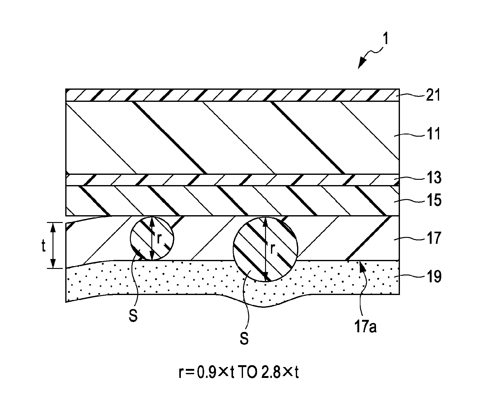
[0018]FIG. 1 is a schematic sectional view showing a principal portion of a configuration example of a thermal transfer sheet 1 to which the present invention is applied. The thermal transfer sheet 1 according to an embodiment shown in FIG. 1 is used for covering (as a laminate) an ink image formed in a print and protecting it. The thermal transfer sheet 1 is configured as described below.

[0019]The thermal transfer sheet 1 includes a primer layer 13, a non-transferable release layer 15, a protective layer 17 including a binder resin 17a containing fine particles S, and an adhesive layer 19, which are laminated in that order on one of the main surfaces of a sheet base material 11. In addition, a heat-resistant slipping layer 21 is provided on the other main surface of the sheet base material 11. According to the first embodiment, the thermal transfer sheet 1 having such a layer configuration has the feature that the particle diameter r of the fine particles is 0.9 ...

second embodiment

2. Second Embodiment

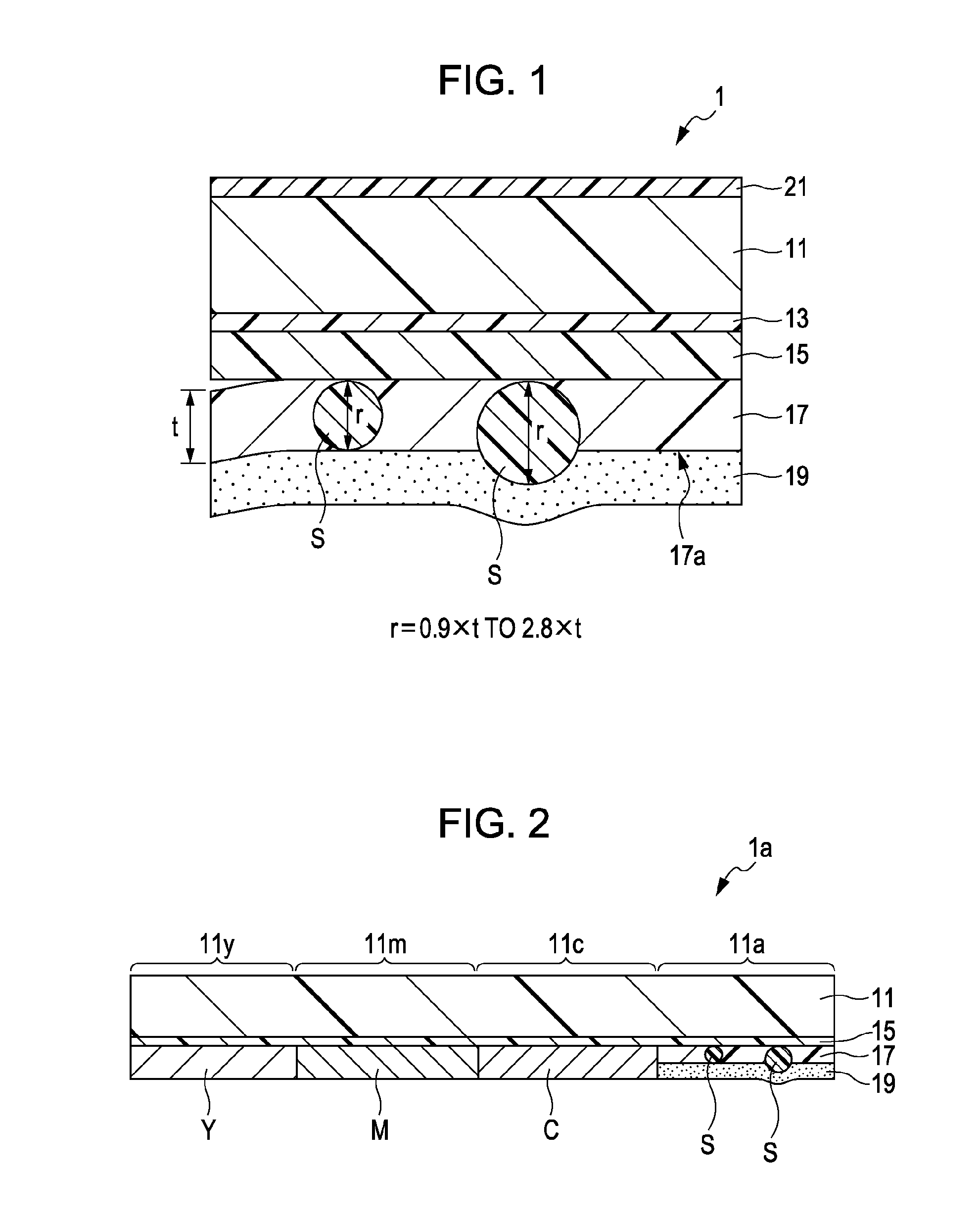
[0037]FIG. 2 is a schematic sectional view showing a principal portion of a configuration example of an ink ribbon 1a to which the present invention is applied. In FIG. 2, the same components as in the first embodiment are denoted by the same reference numerals.

[0038]The ink ribbon 1a according to an embodiment shown in FIG. 2 includes a protective region 11a in which the protective layer 17 described in the first embodiment is provided, and printing regions 11c, 11m, and 11y including ink layers C, M, Y, respectively, the protective region 11a and the printing regions 11c, 11m, and 11y being arranged in planar order in a direction on a sheet base material 11. The configuration of the protective region 11a is the same as that of the thermal transfer sheet described in the first embodiment. The cyan printing region 11c, the magenta printing region 11m, and the yellow printing region 11y are provided with a cyan ink layer C, a magenta ink layer M, and a yellow ink ...

examples 10 to 18

[0071]

TABLE 4RefractiveExampleExampleExampleExampleExampleExampleExampleExampleExampleMaterialindex101112131415161718Non-Polyester resin—10 partstransferableMethyl ethyl—45 partsreleaseketonelayer 15Toluene—45 partsProtectivePMMA1.4910 partslayer 17Cross-linked1.490.2 part 2 parts 3 parts——————PMMA fineparticleSilicone fine1.43———0.2 part 2 parts 3 parts———particleCrosslinked1.59——————0.2 part 2 parts 3 partspolystyrenefine particleToluene—89.8 parts88 parts87 parts89.8 parts88 parts87 parts89.8 parts88 parts87 partsAdhesiveAcrylic resin1.4910 partslayer 19Methyl ethyl—45 partsketoneToluene—45 partsEvaluation of detachabilityGoodGoodGoodGoodGoodGoodGoodGoodGoodEvaluation of glossy feelGoodGoodNearlyNearlyPoorPoorNearlyPoorPoorgoodgoodgood

[0072]A non-transferable release layer 15 was formed on one of the surfaces of a sheet base material 11 including a polyester film of 4.5 μm (K604E4.5W manufactured by Mitsubishi Chemical Polyester Film Co., Ltd.). In this case, a coating solution c...


PUM

PropertyMeasurementUnit
particle diameteraaaaaaaaaa
thicknessaaaaaaaaaa
thicknessaaaaaaaaaa

Abstract

A thermal transfer sheet includes a protective layer and an adhesive layer which are laminated on a sheet base material in that order, the protective layer including a binder resin containing fine particles. The particle diameter of the fine particles is 0.9 to 2.8 times the thickness of the protective layer.

Description

BACKGROUND OF THE INVENTION[0001]1. Field of the Invention[0002]The present invention relates to a thermal transfer sheet and an ink ribbon, and particularly to a thermal transfer sheet being excellent in detachability between a non-transferable release layer and an image protecting layer and being capable of imparting a high glossy feel to prints.[0003]2. Description of the Related Art[0004]Protective layers composed of a thermoplastic resin are laminated on images formed on printing paper, for example, ink images formed by a sublimation thermal transfer method using sublimation or thermal diffusion dyes. The protective layers are imparted with gas cutoff performance and ultraviolet absorbing performance so that discoloration of images can be prevented, and transfer of inks which form images to various articles containing plasticizers, such as erasers and the like can be prevented.[0005]A usual method for laminating a protective layer on an ink image is a method using a thermal tra...

Claims


Application Information

Patent Timeline
Patent Type & Authority Applications(United States)
IPC IPC(8): B41M5/42
CPCB41M5/38214B41M7/0027B41M5/385B41M2205/30B41M5/423B41M5/44B41M5/42
Inventor YASUMATSU, RYO
Owner SONY CORP
Why Eureka
Try Eureka