Mobile communication system, base station, mobile station, and base station installation method

a mobile communication system and installation method technology, applied in the field of mobile communication systems, can solve the problems of not offering the effect of reducing handover failures and eliminating dead spots, unable to eliminate dead spots for base stations, and not offering the effect of reducing dead spots, so as to reduce the rate of handover failures, reduce the number of handovers, and reduce dead spots

Inactive Publication Date: 2010-11-18
MITSUBISHI ELECTRIC CORP
View PDF21 Cites 93 Cited by
  • Summary
  • Abstract
  • Description
  • Claims
  • Application Information

AI Technical Summary

Benefits of technology

[0015]According to the present invention, on the basis of historical information from a mobile station, a base station or a base station host apparatus gives instructions for the specifying of a handover destination for the mobile station or for beam control for the base station, whereby a mobile communication system is established which reduces the rate of handover failures and reduces the number of handovers, and which reduces dead spots to allow the mobile station to stably communicate with the

Problems solved by technology

Also, in the scheme disclosed in Patent Document 2, the base station merely manages signals sent from mobile stations to specify the positions of mobile stations, so that it does not offer the effects to reduce handover failures and eliminate dead spots.
Also, in the scheme disclosed in Patent Document 3, even though an emergency ce

Method used


Image

  • Mobile communication system, base station, mobile station, and base station installation method
  • Mobile communication system, base station, mobile station, and base station installation method
  • Mobile communication system, base station, mobile station, and base station installation method

Examples


first example

A-1. First Example

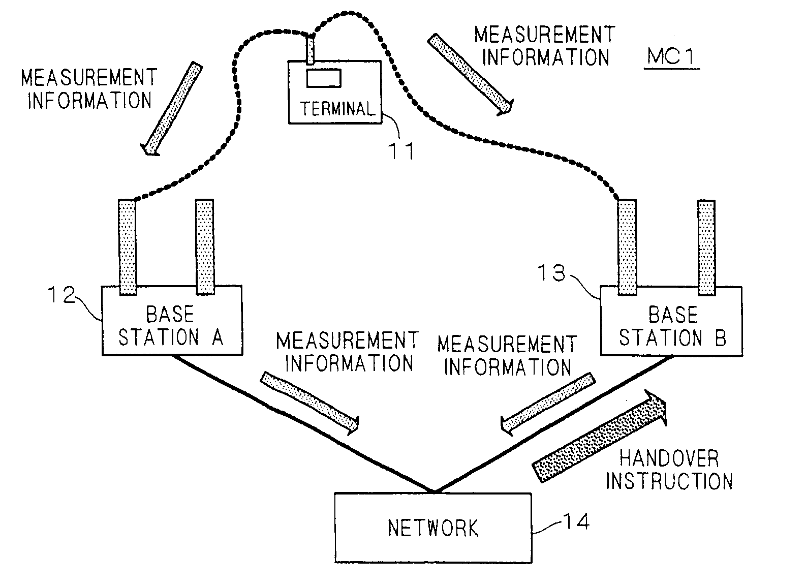
[0063]FIG. 1 illustrates the configuration of a mobile communication system MC1 according to a first example.

[0064]As shown in FIG. 1, the mobile communication system MC1 has a network configuration in which a plurality of base stations, such as a base station 12 and a base station 13, are connected to a base station host apparatus 14 including base station control equipment and core network.

[0065]In FIG. 1, a mobile station (=a terminal) 11 is present between the communication area of the base station 12 (hereinafter referred to as base station A) and the communication area of the base station 13 (hereinafter referred to as base station B).

[0066]Now, the base station A can perform wireless transmission with the mobile station 11, and can also perform wired or wireless data transmission with the base station host apparatus 14, and the base station B also has the same functions as the base station A.

[0067]In the case of W-CDMA (Wideband Code Division Multiple Access...

second example

A-2. Second Example

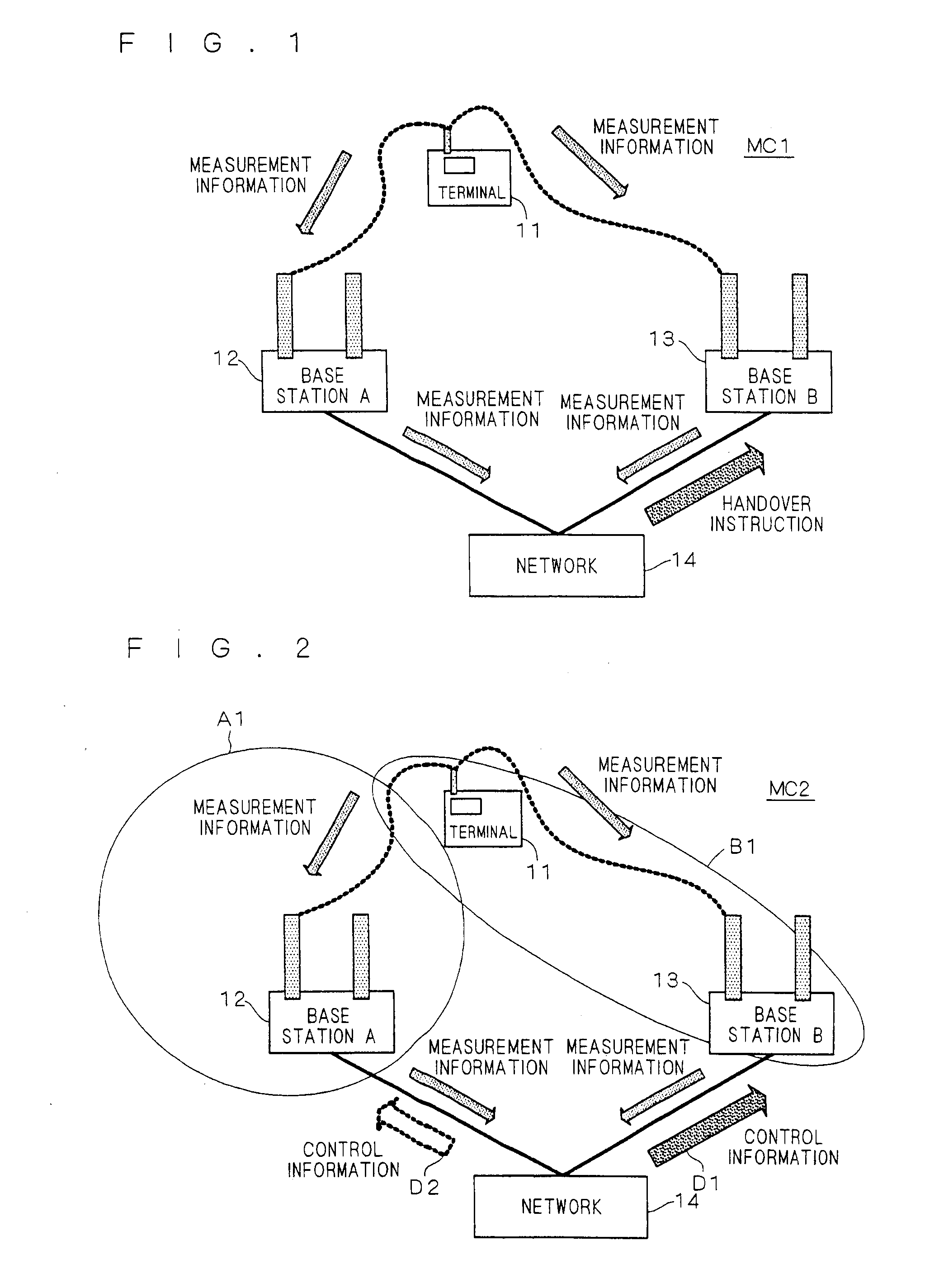
[0074]FIG. 2 illustrates the configuration of a mobile communication system MC2 according to a second example. Similarly to that in FIG. 1, a mobile station 11 is in a place where it is included in both of the communication area of the base station A and the communication area of the base station B, and the mobile station 11 is trying to perform a handover between the two base stations.

[0075]In the mobile communication system MC2 shown in FIG. 2, a base station or base station host apparatus 14 does not specify handover destinations on the basis of historical information from the mobile station 11; the base station host apparatus 14 is configured such that, on the basis of historical information from the mobile station 11, it provides a certain base station with control information to direct communication beam to the mobile station 11 so as to include the mobile station 11 in the communication area, and it provides another base station with control information not...

third example

A-3. Third Example

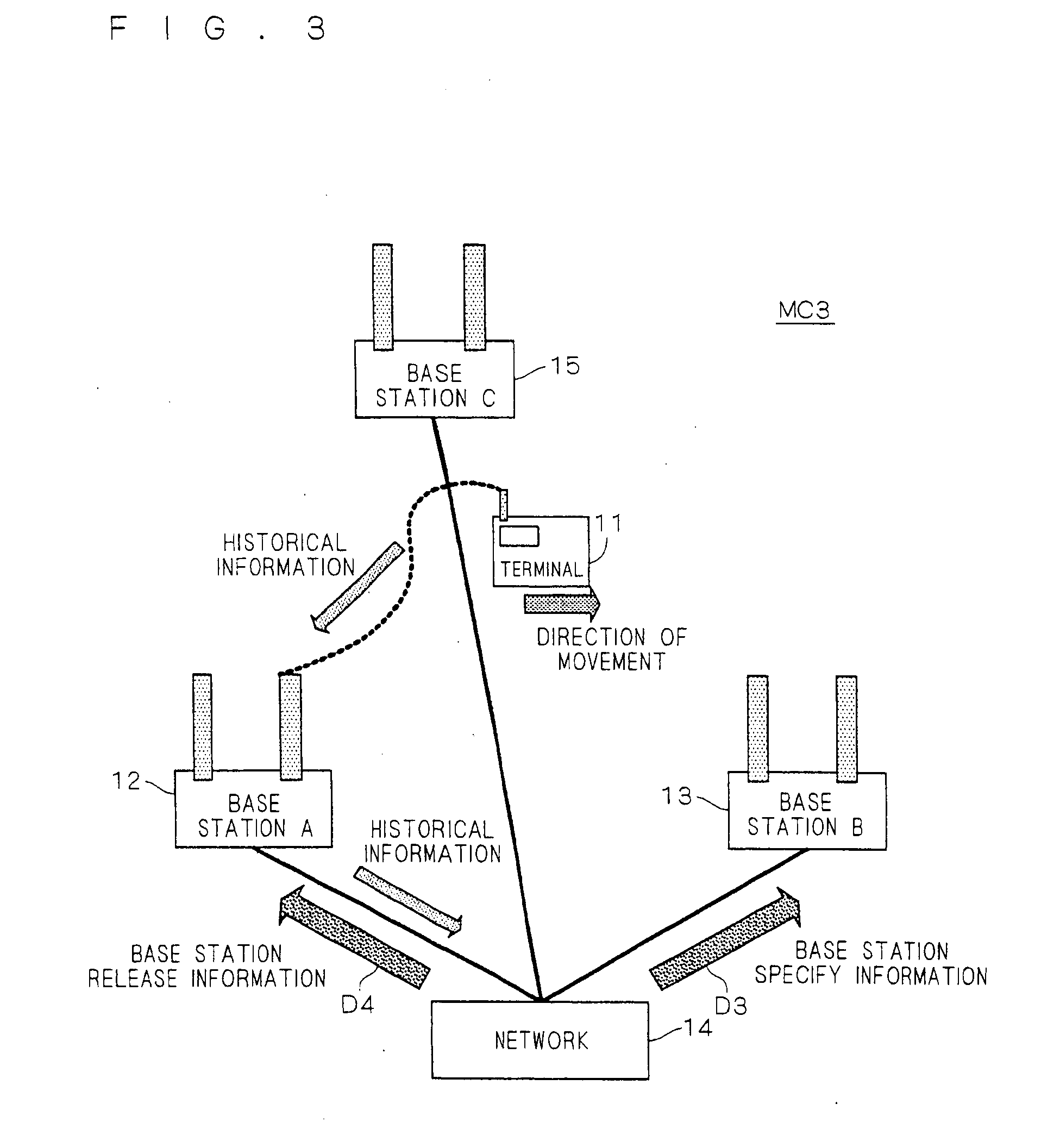
[0081]FIG. 3 illustrates the configuration of a mobile communication system MC3 according to a third example.

[0082]In the mobile communication system MC3 shown in FIG. 3, not only the base station 12 and the base station 13 but also a base station 15 (hereinafter referred to as base station C) is connected to the base station host apparatus 14. The mobile station 11 is configured to notify base stations of the direction of movement, as behavior information, of the mobile station 11 as its historical information. The mobile station 11 is moving toward the base station B, and it is currently in the communication area of the base station A and communicating with the base station A. However, the mobile station 11 is also reaching the communication area of the base station B and the communication area of the base station C, and it has a history that it has just slightly communicated with the two base stations.

[0083]The mobile station 11 keeps the history, and provides t...


PUM


Abstract

In a mobile communication system, a mobile station is configured to obtain data quality information, and provides the obtained data quality information to a base station A when it is quality information about data from the base station A, and provides the data quality information to a base station B when it is quality information about data from the base station B. The base stations A and B are configured to provide a base station host apparatus with the quality information from the mobile station as historical information about the mobile station, and the base station host apparatus is configured to compare the pieces of quality information sent from the two base stations, select one base station with better quality, instructs it to communicate with the mobile station, and instructs the other not to communicate with the mobile station.

Description

TECHNICAL FIELD[0001]The present invention relates to a mobile communication system in which mobile and base stations communicate with each other.BACKGROUND ART[0002]In mobile communication, as disclosed in Patent Document 1, for example, there is a scheme in which, when a mobile station (mobile node) performs a handover by changing the connected base station, the link bandwidths of the mobile station before and after the handover are compared and an upper layer discards packets of, e.g. TCP (Transmission Control Protocol) / RTP (Real-time Transport Protocol) or adjust the rate. This enables packet handling in accordance with the upper layer and improves communication performance during handover.[0003]Also, as disclosed in Patent Document 2, for example, there is a scheme in which a home memory station that manages positional information about terminals is employed to find a particular terminal moving together with a monitored terminal. This enables finding a particular terminal movin...

Claims


Application Information

Patent Timeline
IPC IPC(8): H04W36/00
CPCH04W36/245H04W36/008375H04W36/30H04W36/32H04W16/28H04W88/02
Inventor SUEMITSU, TAISEISUZUKI, KUNIYUKIKISHISHITA, NARIAKIKATADA, FUTOSHIOKAMOTO, KEIJI
Owner MITSUBISHI ELECTRIC CORP
Why Eureka
Try Eureka