Vehicle air conditioner
a technology for air conditioners and vehicles, applied in the field of vehicles, can solve the problem that air conditioners cannot warm the compartments sufficiently
- Summary
- Abstract
- Description
- Claims
- Application Information
AI Technical Summary
Benefits of technology
Problems solved by technology
Method used
Image

Examples
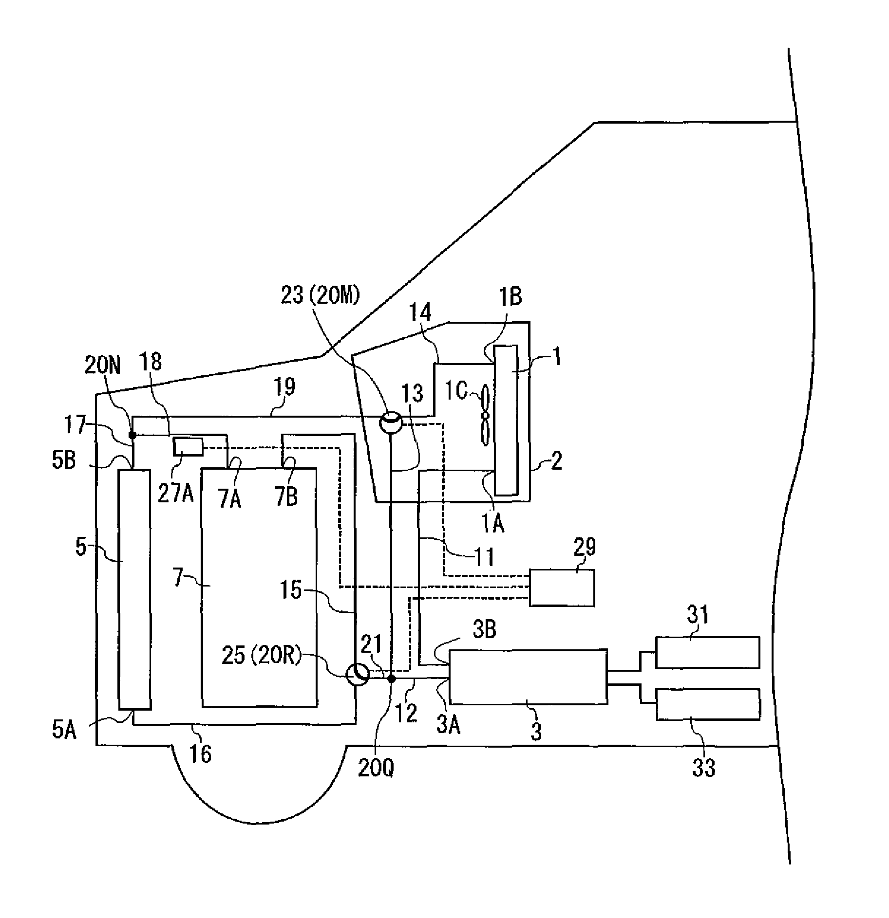
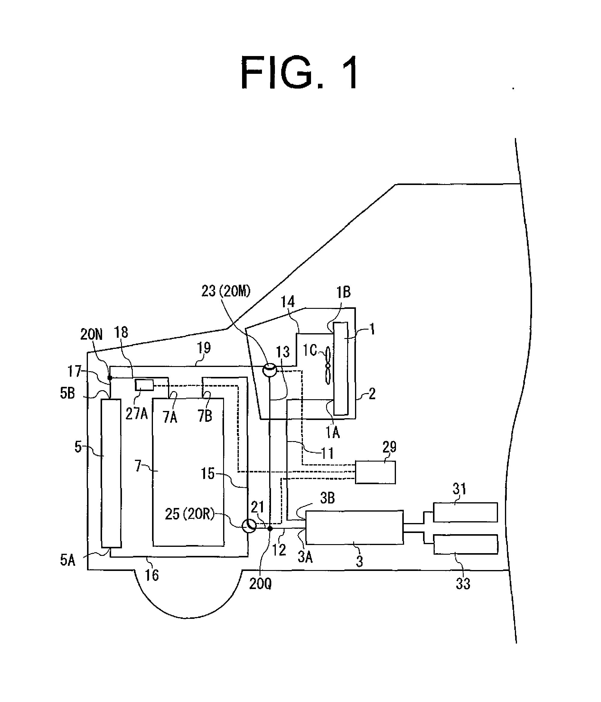
first embodiment
[0043]The vehicle air conditioner is installed in a hybrid or an electric vehicle. As shown in FIG. 1, the vehicle air conditioner includes a heater core 1 as a heat exchanger (hereinafter referred to as a first heat exchanger), a heat storage unit 3, a condenser 5 as a heat exchanger (hereinafter referred to as a second heat exchanger) and a vehicle system 7.
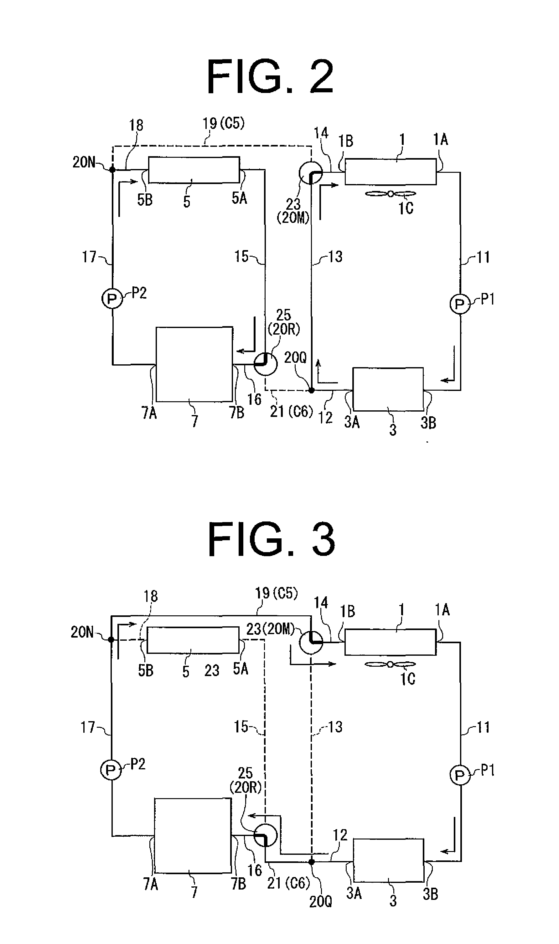
[0044]As shown in FIGS. 2 and 3, the heater core 1 has a first outlet 1A through which water as heat exchange medium flows out and a first inlet 1B through which water flows in. As shown in FIG. 1, the heater core 1 is provided within a duct 2 and a fan 1C is provided at a position adjacent to the heater core 1. When the fan 1C is driven, the air around the heater core 1 is guided by the duct 2 and supplied into a vehicle compartment.
[0045]As shown in FIGS. 2 and 3, the heat storage unit 3 has a second outlet 3A through which water flows out and a second inlet 3B through which water flows in. The heat storage unit 3 has a heat...
seventh embodiment
[0140]In the vehicle air conditioner according to the embodiment, the peltier device 41 is operated by the regenerative electric power. Therefore, the air conditioning of the compartment by heating or cooling the water and the maintenance of the operating performance of the vehicle system 7 can be accomplished while saving energy. The use of the peltier device 41 simplifies the structure of the vehicle air conditioner, thereby facilitating the installation of the vehicle air conditioner and reducing the manufacturing cost. The other advantageous effects are the same as those of the
[0141]The vehicle air conditioner according to the ninth embodiment shown in FIG. 27 is made by adding a battery 99, a battery circulation circuit and a joint circuit to the vehicle air conditioner according to the eighth embodiment.
[0142]The second face heat exchanger 97 of the vehicle air conditioner has a fifth outlet 97A through which water flows out and a fifth inlet 97B through which water flows in.
[...
eighth embodiment
[0163]In the vehicle air conditioner, the battery 99 can be warmed or cooled by the peltier device 41 in addition to the heat stored in the heat storage medium and the exhaust heat of the vehicle system 7. Therefore, the performance deterioration of the battery 99 due to the temperature change can be prevented effectively. Furthermore, the compartment can be also warmed by the heat generated by the battery 99 and the positive heat can be stored in the heat storage medium. Thus, highly energy-saving air conditioning of the compartment can be achieved. The other advantageous effects are the same as those of the
[0164]The present invention has been described with reference to the first through the ninth embodiments. The present invention is not limited to these embodiments, but may be modified within the scope of the appended claims.
[0165]For example, the desiccant type dehumidifier 50 may be added to the vehicle air conditioners according to the second, fourth, seventh, eighth and nint...
PUM
 Abstract
Description
Claims
Application Information
 - Generate Ideas
- Intellectual Property
- Life Sciences
- Materials
- Tech Scout
- Unparalleled Data Quality
- Higher Quality Content
- 60% Fewer Hallucinations
Browse by: Latest US Patents, China's latest patents, Technical Efficacy Thesaurus, Application Domain, Technology Topic, Popular Technical Reports.
© 2025 PatSnap. All rights reserved.Legal|Privacy policy|Modern Slavery Act Transparency Statement|Sitemap|About US| Contact US: help@patsnap.com