
Process and apparatus for producing a hollow body, and hollow body

a hollow body and hollow body technology, applied in the field of metal production methods, can solve the problems of thinning out the thickness of the sheet, increasing the cost of production, and prone to corrosion of the seam, and achieve the effects of high stress, small sheet thickness change, and high strength

Active Publication Date: 2010-11-25
THYSSENKRUPP STEEL EURO AG
View PDF1 Cites 0 Cited by
  • Summary
  • Abstract
  • Description
  • Claims
  • Application Information

AI Technical Summary

Benefits of technology

[0005]Proceeding from this basis, an aspect of the present invention is to provide a method and an apparatus for producing a generic hollow body which can be operated economically and with which hollow bodies having a high strength with shape transitions essentially running in a radial plane and with almost constant sheet thickness can be produced.

Problems solved by technology

In addition, welding seams are susceptible to corrosion and increase the cost of production.
However, these shape transitions generally can only be produced at the ends of tubes and result in a pronounced thinning-out of the sheet thickness.
The same is also true for internal high-pressure shaping, which requires additional high investment with respect to the tools.
Shape transitions essentially running in a radial plane cannot be produced using the rolling-in technique.
However, this method is also cost-intensive, in particular due to the necessary heating.
Furthermore, the sheet thickness reduction is relatively large in the known method.

Method used


Image

  • Process and apparatus for producing a hollow body, and hollow body
  • Process and apparatus for producing a hollow body, and hollow body
  • Process and apparatus for producing a hollow body, and hollow body

Examples


Embodiment Construction

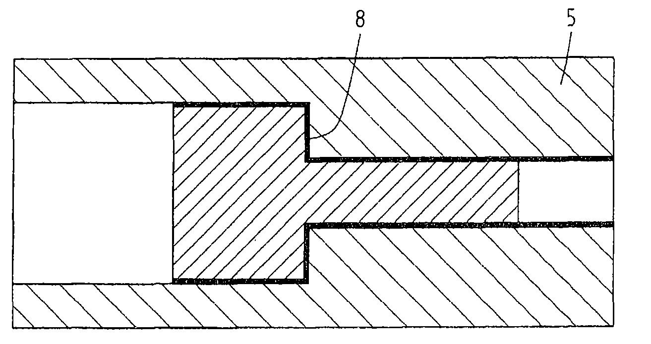
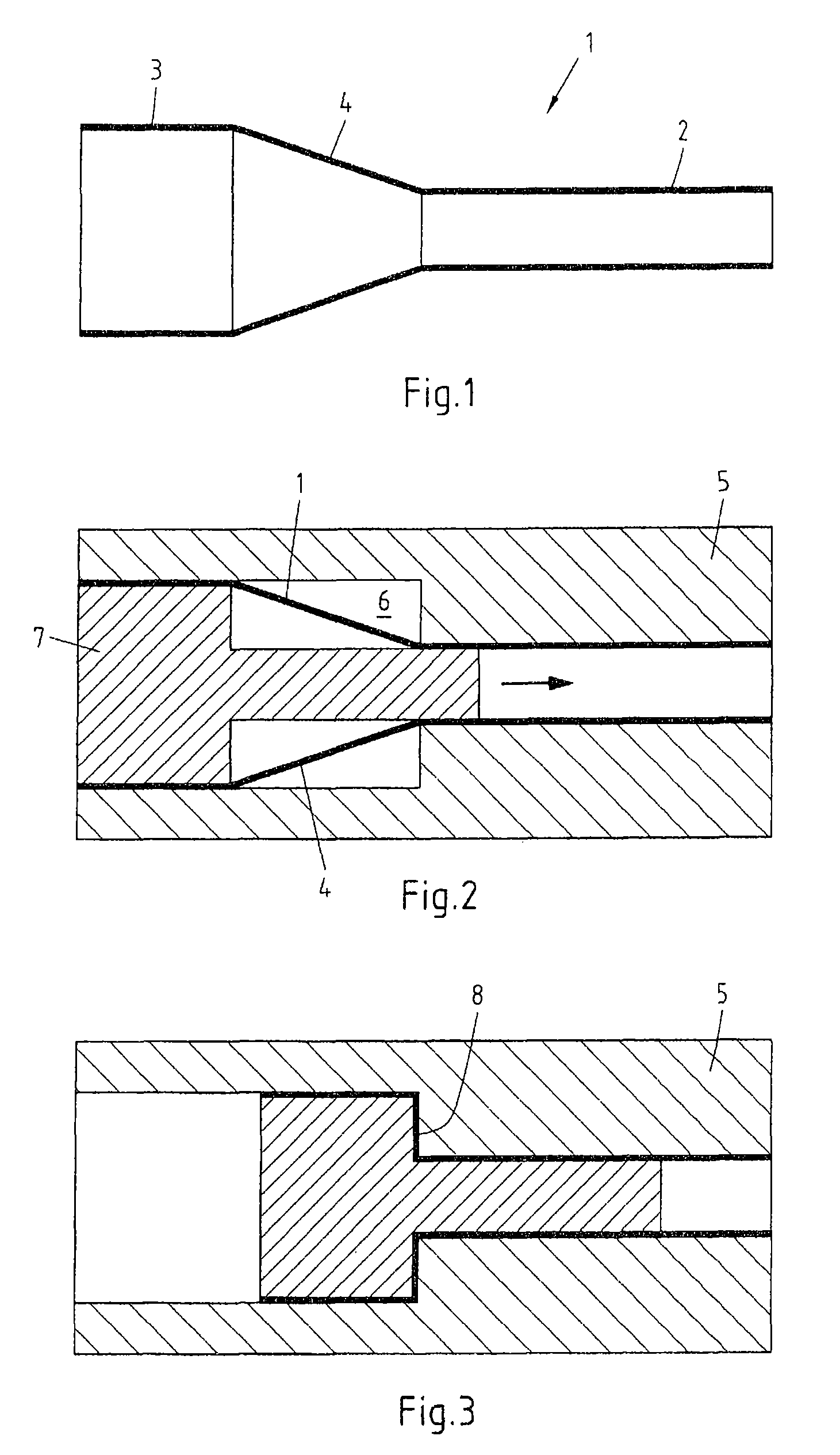
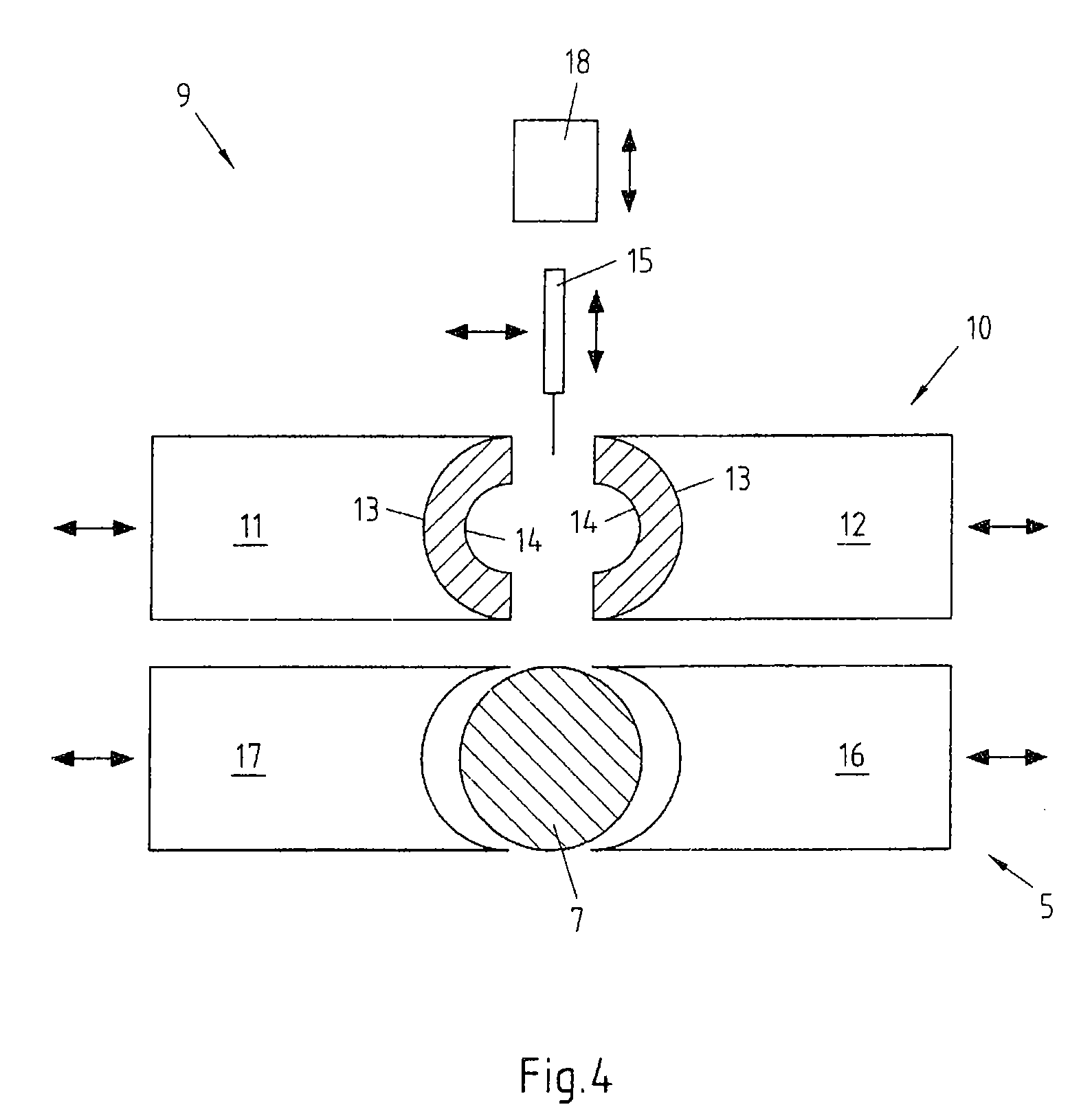
[0024]In FIG. 1 firstly the preform body 1 is illustrated in a schematic, axial sectional view. The preform body has a first axial portion 2 with a first cross-sectional area and a second axial portion 3 with a second cross-sectional area. The cross-sectional area of the first axial portion 2 is smaller than the cross-sectional area of the second axial portion 3. In the transition region 4, extending in the axial direction, which is arranged between the two axial portions 2, 3, the cross-sectional area of the axial portion 2 changes into the cross-sectional area of the axial portion 3. In the exemplary embodiment illustrated, the shape transition is continuous or linear in the transition region 4 extending in the axial direction. However, other shape transitions are also conceivable. The preform body 1 shown in FIG. 1 can, for example, be produced using the rolling-in technique or U-O forming. In this case, the preform body, as also the finished hollow body, has a circular cross-sec...


PUM

PropertyMeasurementUnit
thicknessaaaaaaaaaa
shapeaaaaaaaaaa
axial lengthaaaaaaaaaa

Abstract

A process for producing a metal hollow body comprising a first axial portion with a first cross-sectional area and a second axial portion with a second cross-sectional area, and in which the two axial portions are connected to one another by means of a shape transition running in the axial direction, the method includes producing a preform body having at least one transition region which extends in the axial direction and is arranged between the first and second axial portions, wherein, in the transition region, the cross-sectional area of the preform body continuously changes from the cross-sectional area of the first axial portion into the cross-sectional area of the second axial portion, accommodating the preform body in a die, a shaping mandrel into the preform body, and axially moving the shaping mandrel to upset the preform body in the die into the final shape of the hollow body.

Description

CROSS-REFERENCE TO RELATED APPLICATIONS[0001]This application is a National Phase Application of International Application No. PCT / EP2008 / 064047, filed on Oct. 17, 2008, which claims the benefit of and priority to German patent application no. DE 10 2007 050 337.9-14, filed on Oct. 18, 2007. The disclosures of the above applications are incorporated herein by reference in their entirety.FIELD OF THE INVENTION[0002]The invention relates to a method for producing a hollow body made of metal, which comprises at least one first axial portion with a first cross-sectional area and a second axial portion with a second cross-sectional area and in which both axial portions of the hollow body are connected to one another by means of a shape transition running in a radial plane. Furthermore, the invention relates to an apparatus for carrying out the method.BACKGROUND[0003]In the automobile industry and also in pipe fabrication, hollow bodies, which in the axial direction have large changes of ...

Claims


Application Information

Patent Timeline
Patent Type & Authority Applications(United States)
IPC IPC(8): B21D51/02
CPCB21C37/0815B21D41/02B21D22/025B21C37/185
Inventor FLEHMIG, THOMASGORSCHLUTER, JORGMERTENS, OLIVER
Owner THYSSENKRUPP STEEL EURO AG
Learn More