Brake control system and brake control method

a technology of brake control system and control method, which is applied in the direction of braking system, analogue process for specific applications, instruments, etc., can solve the problems of reducing braking performance and adversely affecting pedal feel, and achieve good pedal feel

Inactive Publication Date: 2010-11-25
TOYOTA JIDOSHA KK
View PDF13 Cites 7 Cited by
  • Summary
  • Abstract
  • Description
  • Claims
  • Application Information

AI Technical Summary

Benefits of technology

[0006]This invention thus provides a brake control system and brake control method capable of achieving good pedal feel.

Problems solved by technology

When an abnormality such as fading occurs in such a brake control system, the hydraulic pressure in the wheel cylinder is insufficient, reducing braking performance.
However, in this case, if the pump starts to be driven while the driver is depressing the brake pedal, brake fluid will flow out of the master cylinder, creating a phenomenon in which the brake pedal is drawn or sucked in, which may adversely affect the pedal feel.

Method used


Image

  • Brake control system and brake control method
  • Brake control system and brake control method
  • Brake control system and brake control method

Examples


Embodiment Construction

[0017]Example embodiments of the present invention will be described in greater detail below with reference to the accompanying drawings.

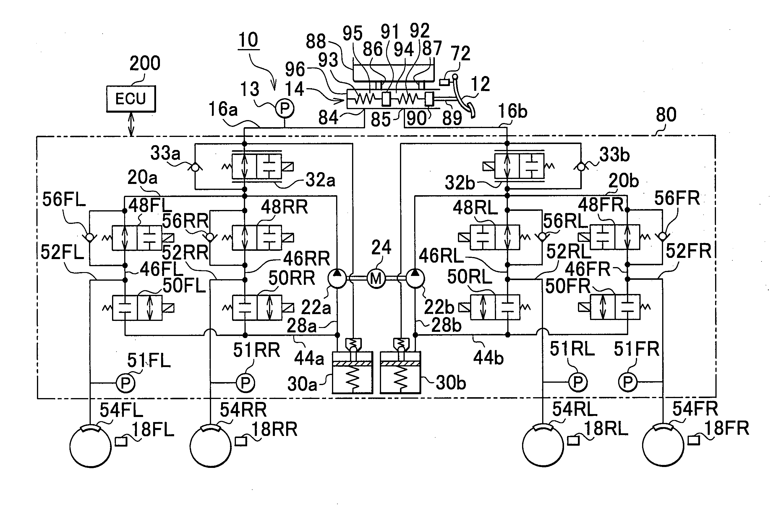
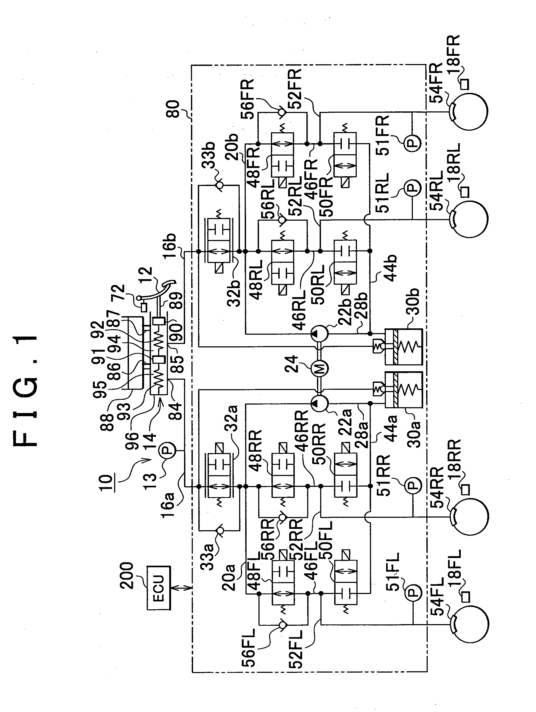
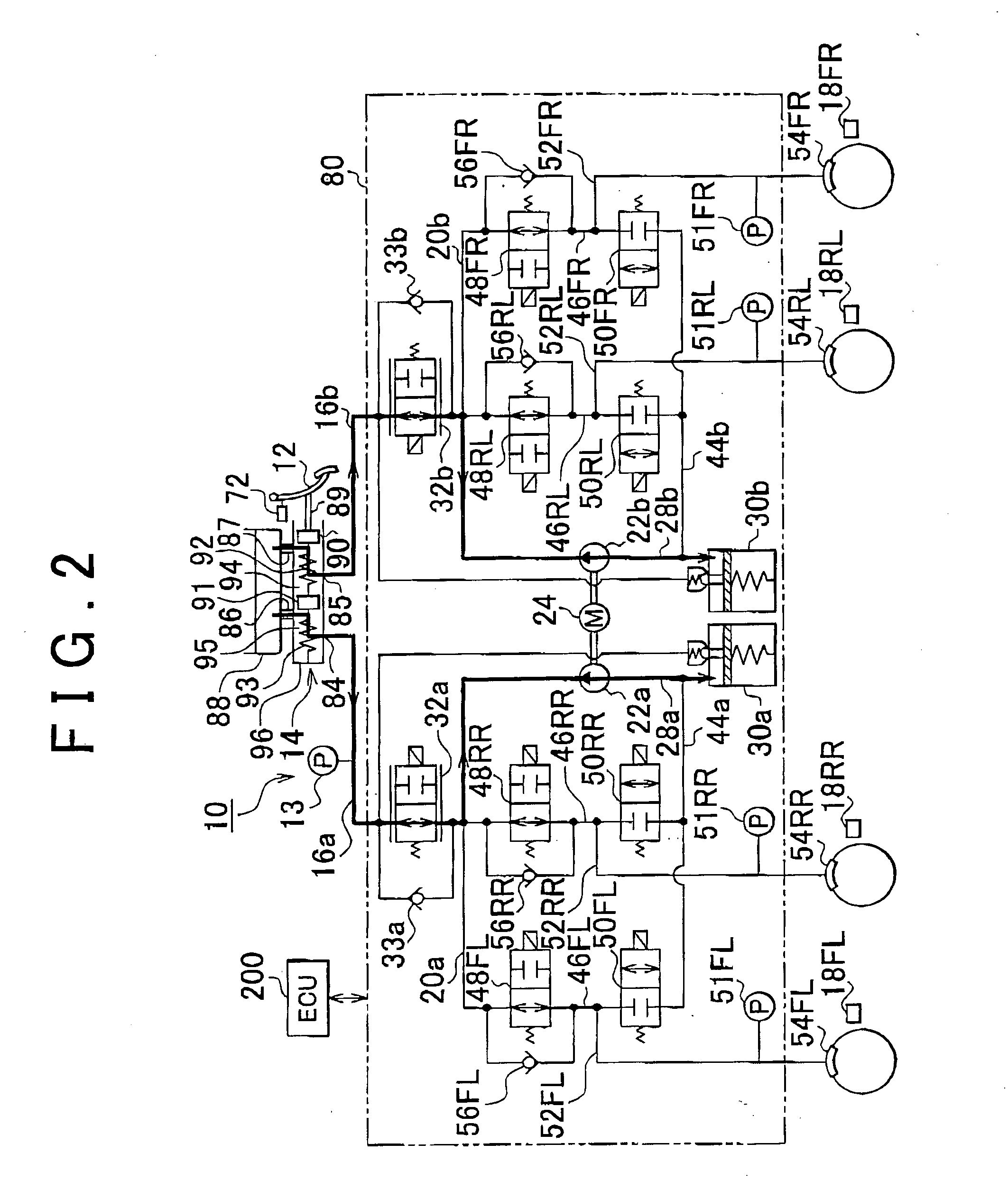
[0018]FIG. 1 is a diagram of the structure of a brake control system 10 according to an example embodiment of the invention. The hydraulic circuit in the brake control system 10 shown in FIG. 1 is configured as a diagonally split system in which a system for the left front wheel and the right rear wheel is independent of a system for the right front wheel and the left rear wheel. Therefore, if one of the systems was to fail, the other system would still be able to function reliably.

[0019]The brake control system 10 includes a master cylinder 14 that generates hydraulic pressure corresponding to the depression amount of a brake pedal 12, which serves as a brake operating member, by a driver. The master cylinder 14 has a first piston 90 slidably housed in a cylinder housing 96. A piston rod 89 that is connected to the brake pedal 12 is formed on one ...


PUM


Abstract

A brake control system includes a wheel cylinder, a brake pedal, a master cylinder in which communication between it and an external master cylinder reservoir is cut off when the operating amount of the brake pedal is equal to or greater than a predetermined value, an internal reservoir, and a pump which selectively discharges hydraulic fluid in two directions, one being a direction that increases the hydraulic pressure in the wheel cylinder by drawing up hydraulic fluid from the internal reservoir, and the other being a direction that stores hydraulic fluid in the internal reservoir. The pump is driven to discharge hydraulic fluid in the direction that stores hydraulic fluid when communication is open between the master cylinder and the master cylinder reservoir, and driven to discharge hydraulic fluid in the direction that increases the hydraulic pressure when communication is cut off between the master cylinder and the master cylinder reservoir. A further invention is directed to a brake control method.

Description

BACKGROUND OF THE INVENTION[0001]1. Field of the Invention[0002]The invention relates to a brake control system and brake control method which controls braking force applied to a wheel of a vehicle.[0003]2. Description of the Related Art[0004]Japanese Patent Application Publication No. 9-58445 (JP-A-9-58445), for example, describes a brake control system which controls the braking force of a vehicle such as an automobile and is provided with a reservoir in a hydraulic circuit.[0005]When an abnormality such as fading occurs in such a brake control system, the hydraulic pressure in the wheel cylinder is insufficient, reducing braking performance. In this case, it is desirable to drive a pump in the hydraulic circuit to increase the hydraulic pressure in the wheel cylinder to maintain the required braking force. However, in this case, if the pump starts to be driven while the driver is depressing the brake pedal, brake fluid will flow out of the master cylinder, creating a phenomenon i...

Claims


Application Information

Patent Timeline
Patent Type & Authority Applications(United States)
IPC IPC(8): B60T13/16B60T7/04B60T13/18G06F19/00B60T8/171B60T8/00
CPCB60T8/4063B60T8/4872B60T8/442
Inventor MIYAZAKI, TETSUYA
Owner TOYOTA JIDOSHA KK
Why Eureka
Try Eureka