Piston with improved displacement properties

a technology of displacement properties and pistons, applied in the field of brake pistons, can solve the problems of reducing the working efficiency of brakes, reducing the efficiency of brakes, and reducing the radial force exerted on the closed end of pistons, so as to reduce the failure rate of pistons, reduce the thickness of walls, and reduce the effect of failure ra

Inactive Publication Date: 2013-01-08
AKEBONO BRAKE
View PDF12 Cites 7 Cited by
  • Summary
  • Abstract
  • Description
  • Claims
  • Application Information

AI Technical Summary

Benefits of technology

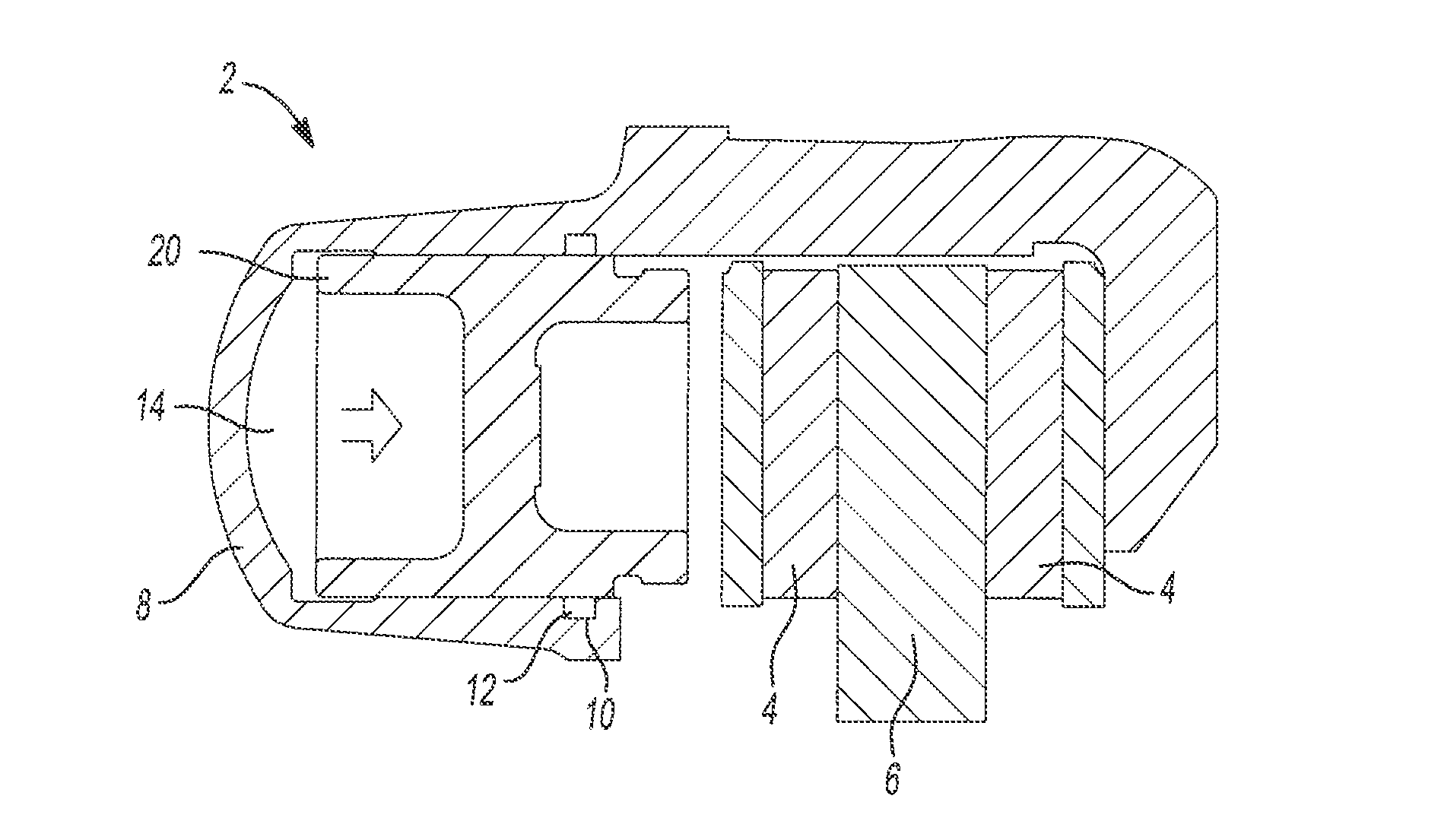
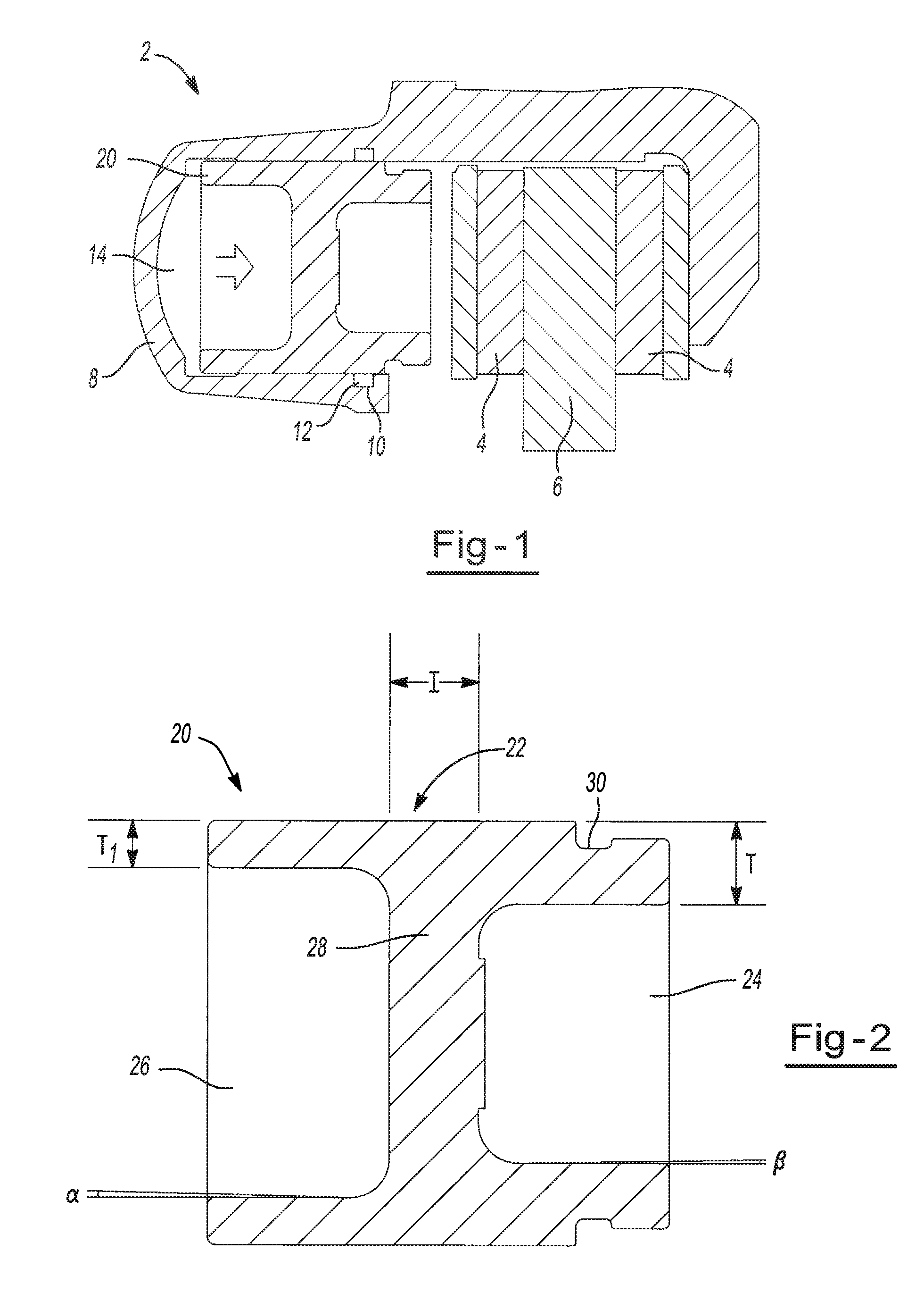
[0006]One unique aspect of the present invention envisions a brake piston that does not include a closed end. The present inventors have identified that if the piston includes two open pockets the radial forces that act upon the open pockets may be equalized. For example, the radial forces pushing on the inside of the pocket walls may be equalized by the radial forces of the fluid pushing on the outside of the piston walls. Thus, the only forces acting upon the piston are axial forces, and piston failures may be reduced and / or eliminated. Furthermore, manufacturability of a piston that includes two open pockets may be performed easier and quicker (e.g. by reducing draft, draft angle, depth of one or more of the pockets, or a combination thereof).
[0007]Another unique aspect of the present invention envisions a reduced wall thickness. The wall thickness of the first pocket, second pocket, or both may be reduced. By reducing the thickness of the piston walls the mass of the piston may be reduced. However, the present invention may create a stiff piston so that materials may be displaced from one area to another area. For example, the wall thickness of one wall may be reduced and the wall thickness of another wall may be increased so that even stronger piston may be created. In another example, the walls of the cylindrical wall may be reduced and the internal wall may be increased; thus, reducing fluid displacement and creating a better pedal feel for the user. Accordingly, it has been identified by the present inventors that it is important to employ a particular design for pistons that makes them stronger, lighter, more resistant to failure, decreases fluid displacement, or a combination thereof.

Problems solved by technology

One disadvantage faced by these pistons is that the radial forces exerted on the closed end of the piston are relatively large.
Due to the relatively large amount of radial force exerted on the closed end of the piston, the walls of the piston fail and the brake ceases to function properly.
The added thickness of the piston walls increases the overall weight of the piston.
However, the wall thickness of some pistons are not increased.
These pistons are subject to an increased piston failure rate.
Another disadvantage faced by known pistons is that the choice of materials for use in creating the piston are limited.
The steel is machined in order to create a piston, and due to the limitations in the machining process the possible configurations of the piston are limited.

Method used


Image

  • Piston with improved displacement properties
  • Piston with improved displacement properties

Examples


Embodiment Construction

[0010]The following description of the preferred embodiment(s) is merely exemplary in nature and is in no way intended to limit the invention, its application, or uses.

[0011]The present invention is predicated upon providing an improved disc brake system and caliper for use with vehicles. For example, the caliper and piston may be used with almost any vehicle (e.g. car, truck, bus, train, airplane, or the like). Alternatively, the caliper and piston may be integrated into components used for manufacturing or other equipment that require a brake such as a lathe, winder for paper products or cloth, amusement park rides, or the like. However, the present invention is most suitable for use with a passenger vehicle (i.e. a car, truck, sports utility vehicle, or the like).

[0012]Generally, a braking system includes a rotor and a caliper body. The caliper body includes an inboard brake pad and an outboard brake pad that are on opposing sides of the rotor. The caliper body further includes a...


PUM


Abstract

A brake pad actuating device comprising: a piston including: a first pocket; an opposing second pocket; and an internal wall located in the piston separating the first pocket and the second pocket, wherein the volume of the first pocket to the volume of the second pocket form a ratio of less than about 20:1; and wherein the piston is adapted to be used as a brake piston.

Description

FIELD OF THE INVENTION[0001]The present invention generally relates to a brake piston and more particularly a piston with two open end portions.BACKGROUND OF THE INVENTION[0002]Typical, pistons used in a brake include one open end and one closed end. The open end faces the brake pad and the closed end is in contact with the brake fluid. When brake pressure is applied the fluid pressure increases and the fluid pushes on the closed end of the piston. The fluid moves the open end of the piston axially, with respect to a rotor, into contact with the brake pad so that the brake pad contacts the rotor and creates a braking force. The fluid pressure exerts both an axial force on the piston and a radial force on the piston. The axial forces on the piston move the piston into contact with the brake pad. Examples of such pistons are disclosed in U.S. Pat. Nos. 4,193,179; 6,637,317; and 7,000,526 all of which are expressly incorporated herein by reference for all purposes.[0003]One disadvantag...

Claims


Application Information

Patent Timeline
Patent Type & Authority Patents(United States)
IPC IPC(8): B60T11/00F16D65/18
CPCF16J1/001B60T1/08F16D2125/06F16D2200/0004F16D2200/0034
Inventor ALAMIN, AMARROSZMAN, ERIC J.
Owner AKEBONO BRAKE
Why Eureka
Try Eureka