Negative pressure doubling device

a technology of negative pressure and doubling device, which is applied in the direction of braking system, vehicle components, servomotors, etc., can solve the problems of affecting the performance of the brake, so as to achieve the effect of preventing the effect of reducing the pressure, facilitating the pedal feeling, and rapid output increas

Pending Publication Date: 2007-01-04
BOSCH CORP
View PDF3 Cites 3 Cited by
  • Summary
  • Abstract
  • Description
  • Claims
  • Application Information

AI Technical Summary

Benefits of technology

[0019] Still further, according to the negative pressure booster of the present invention, by controlling the start of the operation of the rapid output increase means using the indentation quantity of the reaction disc which is generated by a pushing force from the valve plunger based on the input, when the output larger than the output during the usual operation is rapidly necessary in emergency and the like, it is possible to surely perform the assist operation using the rapid output increase means. On the other hand, even when the input member is rapidly operated than the usual operation in spite of the fact that the output larger than the output during the usual operation is not necessary rapidly, the undesired assist operation by the rapid output increase means can be prevented.
[0020] Further, since the position of the valve plunger which is the position at which the assist operation is started is controlled using the reaction disc, it is possible to adjust the threshold value based on the input. Accordingly, it is possible to obtain the favorable pedal feeling during the emergency operation.
[0021] Particularly, assuming that the negative pressure booster of the present invention is used as the brake booster, when the braking force larger than the braking force during the usual operation is rapidly necessary as in the case of the braking operation in emergency and the like, it is possible to surely perform the brake assist operation using the rapid output increase means. On the other hand, when the input shaft is more rapidly operated than the input shaft operated during the usual operation in spite of the fact that the braking force larger than the braking force during the usual operation is not necessary rapidly, it is possible to prevent the undesired brake assist operation by the rapid output increase means.
[0022] Further, during the assist operation, the operation adopts the two-stage input-output characteristics in which the input-output characteristics of the negative pressure booster make a servo ratio in a low input-output region and a servo ratio in a high input-output region different from each other. Accordingly, it is possible to apply an emergency braking corresponding to needs of a driver in a more reliable manner and hence, the driver can obtain the more favorable pedal feeling during the emergency braking.
[0023] Further, since the undesired assist operation can be prevented, it is possible to reduce the number of occurrence of uncomfortable sounds during the assist operation and, at the same time, it is possible to reduce the number of operations of the rapid output increase means and hence, the durability of the rapid output increase means can be enhanced.
[0024] Further, since the assist operation of the rapid output increase means is controlled based on the indentation quantity of the reaction disc, it is sufficient to add some constitutional parts such as a sleeve and the like to the reaction disc, the holder and the valve plunger which are provided to the general negative pressure booster conventionally. Accordingly, it is possible to simplify the structure of the rapid output increase means and, at the same time, the rapid output increase means can be easily assembled and the manufacturing cost can be reduced.

Problems solved by technology

Accordingly, in the negative pressure booster disclosed in the above-mentioned Japanese Patent Laid-open Publication, the structure of the mechanical BA is extremely cumbersome and, at the same time, there have been also drawbacks that the assembling thereof takes time and efforts and pushes up a cost.

Method used


Image

  • Negative pressure doubling device
  • Negative pressure doubling device
  • Negative pressure doubling device

Examples


first embodiment

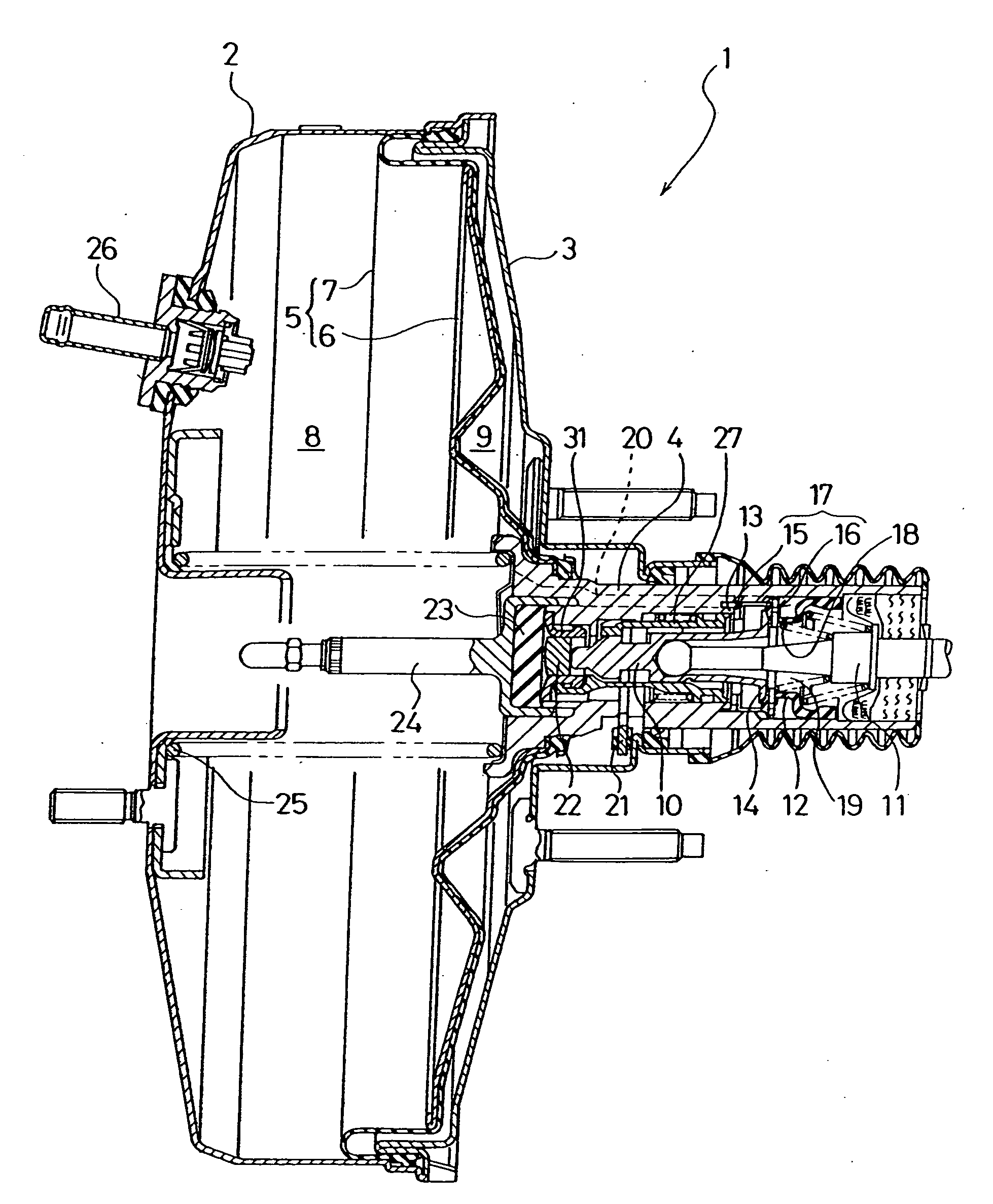
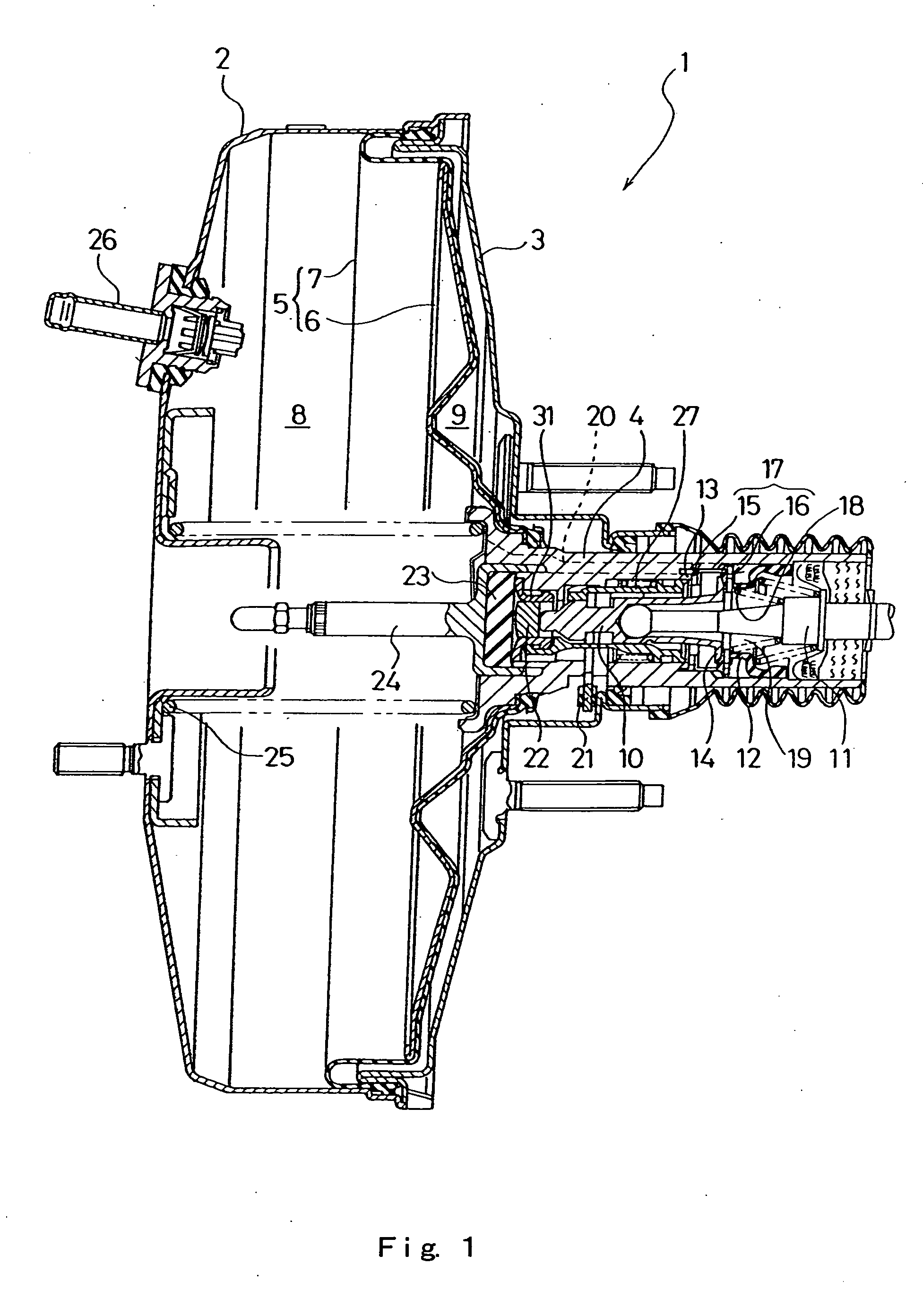
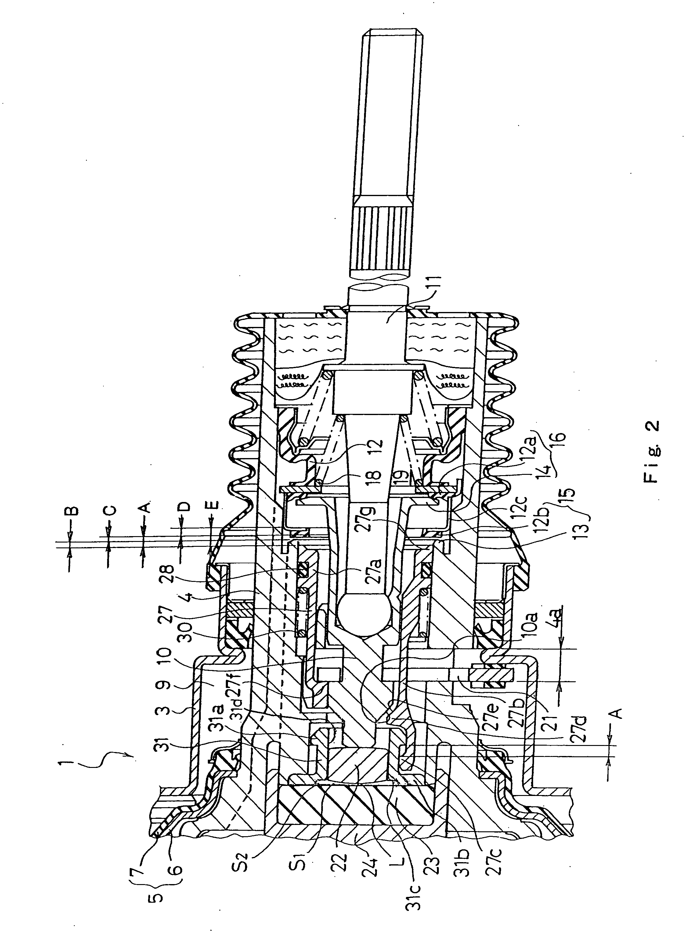
[0036] First of all, in the negative pressure booster of this first embodiment, constitutional parts which are the same as the corresponding constitutional parts of a conventional general negative pressure booster are explained briefly only by reference to symbols. In FIG. 1 and FIG. 2, numeral 1 indicates the negative pressure booster, numeral 2 indicates a front shell, numeral 3 indicates a rear shell, numeral 4 indicates a valve body, numeral 4a indicates a key groove, numeral 5 indicates a power piston, numeral 6 indicates a power piston member, numeral 7 indicates a diaphragm, numeral 8 indicates a constant pressure chamber, numeral 9 indicates a variable pressure chamber, numeral 10 indicates a valve plunger which constitutes an input member of the present invention, numeral 11 indicates an input shaft which constitutes an input member of the present invention, numeral 12 indicates a valve element, numeral 13 indicates a vacuum valve seat, numeral 14 indicates an atmospheric v...

second embodiment

[0104] By forming the sleeve 32 in this manner, as indicated by a chain double-dashed line in FIG. 8, with respect to inclinations of the threshold lines of the second embodiment, the first threshold line in the low input-output region is set to a value equal to the servo ratio SR3 during the usual braking operation, while a second threshold line in the high input-output region is set to a value equal to the servo ratio SR4 which is smaller than the servo ratio SR3.

[0105] Other constitution of the negative pressure booster 1 of the second embodiment is substantially as same as the constitution of the above-mentioned first embodiment.

[0106] Next, the manner of operation of the negative pressure booster 1 of the second embodiment is explained. (The negative pressure booster during the inoperative state) As shown in FIG. 7(a), during the inoperative state of the negative pressure booster, the rear end of the outer flange 32a of the sleeve 32 comes into contact with the bottom portion ...


PUM


Abstract

In a negative pressure booster of the present invention, a threshold line for starting a BA operation at a pedal step-in speed equal to or more than a predetermined speed is set, an inclination of the threshold line is set to a value equal to a servo ratio SR2 smaller than a servo ratio SR1 during a usual braking operation in a low input region (a small pedal step-in region) and is set to a value equal to the servo ratio SR1 during the usual braking operation in a high input region (a large pedal step-in region). That is, the threshold line for starting the BA operation is adjustable between the high input time and the low input time. Further, even when a brake pedal is stepped in at the step-in speed equal to or more than the predetermined speed in spite of a fact that the time when the braking is performed is not an emergency time, the BA operation is not performed and hence, an undesired BA operation can be prevented. In emergency and, at the same time, when the brake pedal is stepped in at the step-in speed equal to or more than the predetermined speed and with a step-in force equal to or more than a predetermined step-in force, the BA operation is started.

Description

BACKGROUND ART [0001] The present invention relates to a technical field of a negative pressure booster which is used in a brake booster or the like, and more particularly to a technical field of a negative pressure booster which can obtain, during an emergency operation such as during an emergency braking operation, an output larger than an output which is obtainable during a usual braking operation. [0002] Conventionally, in a brake system of a vehicle such as an automobile, a negative pressure booster which makes use of negative pressure has been used in a brake booster. In such a conventional generally-used negative pressure booster, the interior of the negative pressure booster is partitioned into a constant pressure chamber into which negative pressure is introduced during the usual operation using a power piston and a variable pressure chamber in which the pressure varies. Further, during the usual braking operation with a usual step-in motion of a brake pedal, when an input ...

Claims


Application Information

Patent Timeline
Patent Type & Authority Applications(United States)
IPC IPC(8): F15B9/10B60T8/32B60T13/569B60T13/573
CPCB60T8/3275B60T13/573B60T13/569B60T13/66
Inventor INOUE, HIDEFUMITAKASAKI, YOSHIYASU
Owner BOSCH CORP
Why Eureka
Try Eureka