Manufacture and use of planar embedded magnetics as discrete components and in integrated connectors

a technology of embedded magnetics and integrated connectors, applied in the field of communication technologies, can solve the problems of poor repeatability and performance, falling into disuse, and difficult control

Active Publication Date: 2010-11-25
PLANARMAG
View PDF70 Cites 47 Cited by
  • Summary
  • Abstract
  • Description
  • Claims
  • Application Information

AI Technical Summary

Problems solved by technology

This is time consuming and offers poor repeatability and performance since the magnetic units 106 are in close proximity and their spacing is difficult to control.
Some efforts have been made to delineate the position of these units using guideposts or grooves in the housing but these have fallen into disuse due to cost and manufacturing cycle times. Controlling leakage and balancing primary and secondary turns across center tap is virtually impossible with these hand wound parts.
Furthermore for higher frequency application it is not possible to control impedance and achieve wideband performance.
Finally these components cannot be used to create subsystems and modules because of the inherent variations from hand winding.
While this offers an improvement over other attempts it still offers limited performance since the magnetics are still hand wound and then placed, which limits performance and increases manufacturing cost.
The current hand wound magnetic solutions do not satisfy this need due to mechanical constraints and hand assembly.
Critical parasitic parameters cannot be controlled such as leakage inductances and capacitive coupling this causes poor performance.

Method used


Image

  • Manufacture and use of planar embedded magnetics as discrete components and in integrated connectors
  • Manufacture and use of planar embedded magnetics as discrete components and in integrated connectors
  • Manufacture and use of planar embedded magnetics as discrete components and in integrated connectors

Examples


Embodiment Construction

[0047]Although the following detailed description contains many specifics for the purposes of illustration, anyone of ordinary skill in the art will readily appreciate that many variations and alterations to the following exemplary details are within the scope of the invention. Accordingly, the following preferred embodiment of the invention is set forth without any loss of generality to, and without imposing limitations upon, the claimed invention.

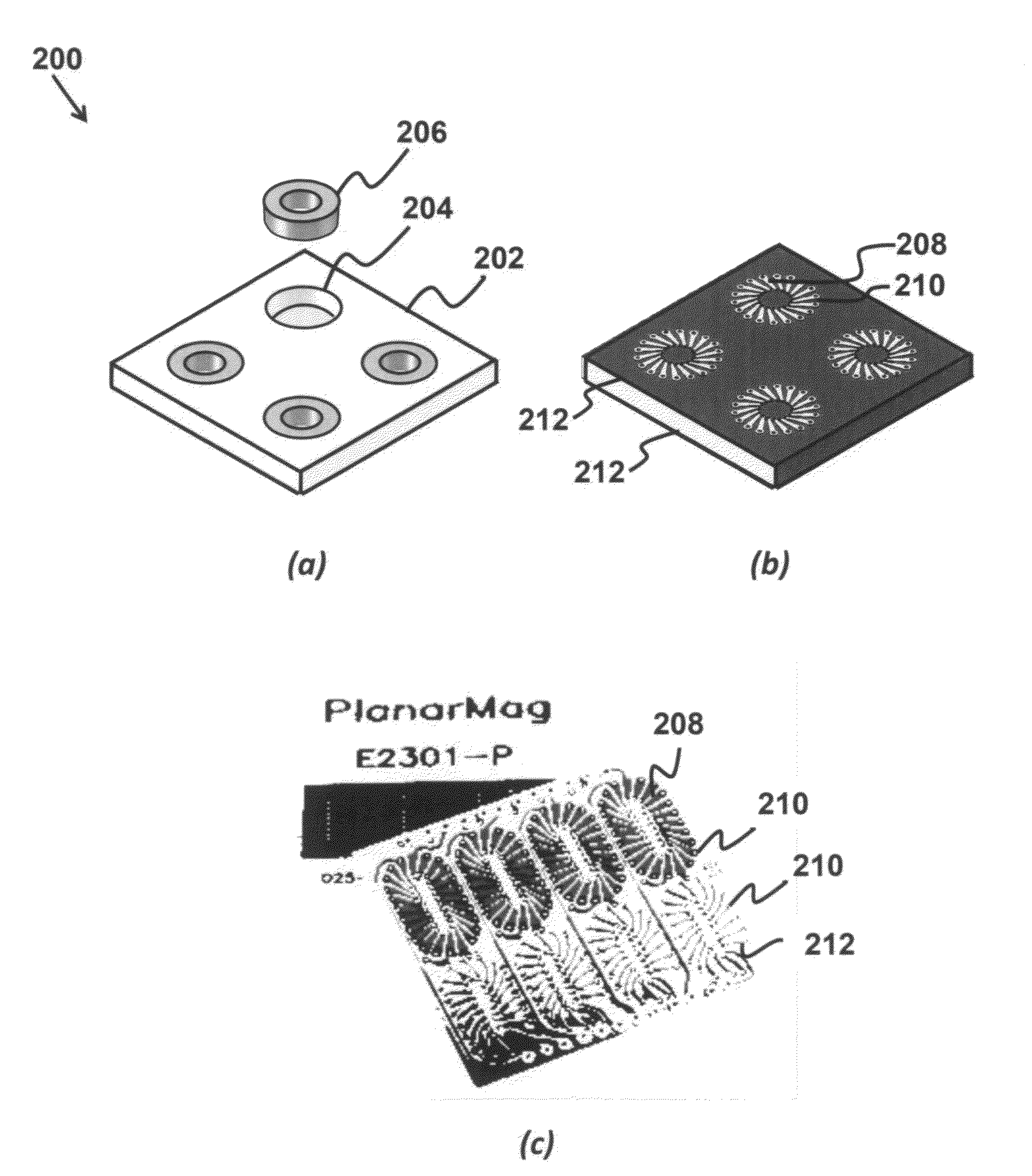
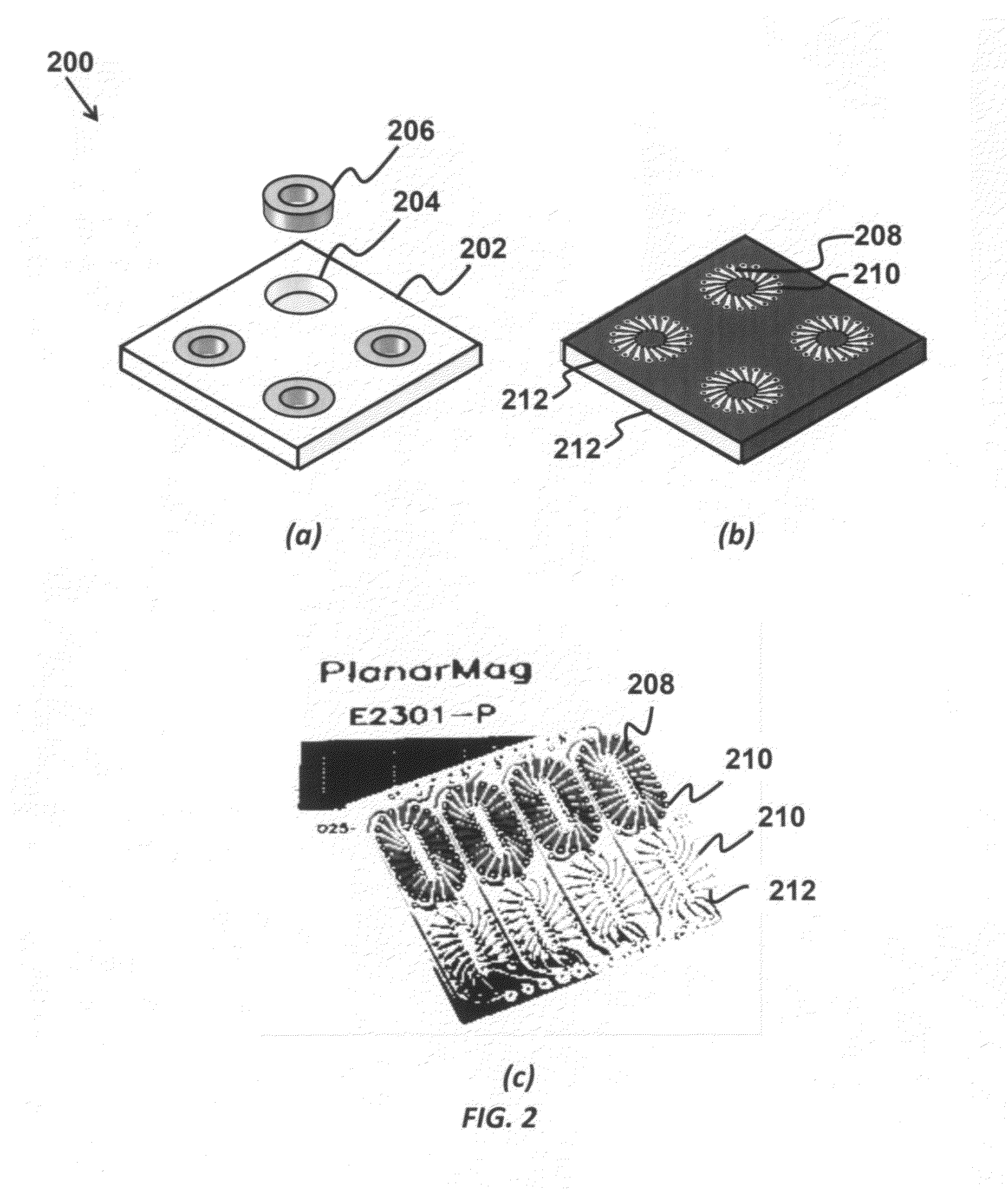
[0048]The current invention includes planar magnetics in which the ferrites or magnets are embedded as a component into a base dielectric material having pre-formed openings, where the pre-formed openings can be molded, routed mechanical drilled, or punched for the magnetic (ferrites) units. These are then encapsulated in a low-stress adhesive, such as a low-stress epoxy, disposed to provide a proper electrical environment. Layers of copper in conjunction with vias enable a magnetic structure, previously created by hand winding units, in ...


PUM

PropertyMeasurementUnit
leakage inductanceaaaaaaaaaa
frequencyaaaaaaaaaa
distanceaaaaaaaaaa

Abstract

The current invention provides an integrated planar transformer and electronic component that includes at least one wideband planar transformer disposed in a planar substrate, where each wideband planar transformer includes a planar substrate in a fully-cured and rigid state, a ferrite material embedded in the planar substrate, where the ferrite material is enveloped in an elastic and non-conductive material, inter-wound conductors disposed around the embedded ferrite material, where top and bottom conductors are bonded by an insulating adhesive. The top and bottom conductors are connected in an inter-connected pattern by conductive vias disposed on each side of the ferrite material and span through the layers to the conductors. The planar transformer further includes at least one center tap connected to at least one inter-wound conductor. The integrated planar transformer and electronic component further includes at least one electronic component connected to at least one terminal of the wide-band planar transformer.

Description

CROSS-REFERENCE TO RELATED APPLICATIONS[0001]This application is a continuation in part to and claims the benefit from U.S. patent application Ser. No. 12 / 006,822 filed Jan. 4, 2008 which claims benefit from U.S. provisional application 60 / 880,208 filed Jan. 11, 2007, and this application also claims benefit from U.S. Provisional Application 61 / 200,809 filed Dec. 3, 2008, and from U.S. Provisional Application 61 / 204,178 filed Dec. 31, 2008, which are hereby incorporated by reference.FIELD OF THE INVENTION[0002]The present invention relates generally to communication technologies. More particularly, the invention relates to a method of creating embedded planar magnetic components, and integrating planar magnets into communication connectors.BACKGROUND[0003]Connectors have been used in the communications industry since it was originally developed for voice traffic. Connectors have gone through a number of evolutions so that it can support current 10G / 1G / 100 / 10 Mbps Ethernet. This tech...

Claims


Application Information

Patent Timeline
Patent Type & Authority Applications(United States)
IPC IPC(8): H01F27/29H01F5/00H01F27/28
CPCH01F17/0033H01F19/04H01F30/16H01F41/046H01R13/6633H01R24/64H05K1/0233H05K1/183H05K2201/086H05K2201/10189H01R13/719
Inventor HARRISON, WILLIAM LEEPHAM, AND-VUQUILICI, JAMES E.DALMIA, SIDHARTHKUBES, STEVEN R.
Owner PLANARMAG
Why Eureka
Try Eureka