
Random Delay Generation for Thin-Film Transistor Based Circuits

a technology of random delay and transistor, applied in the field of wireless communication circuits, can solve the problems of limited number of transistors which may be available for implementing relatively complex circuit functions, and the complexity of circuitry which may be based on tft technology is typically limited, so as to achieve the effect of low cost and low cos

Inactive Publication Date: 2010-11-25
ENSURGE MICROPOWER ASA
View PDF18 Cites 8 Cited by
  • Summary
  • Abstract
  • Description
  • Claims
  • Application Information

AI Technical Summary

Benefits of technology

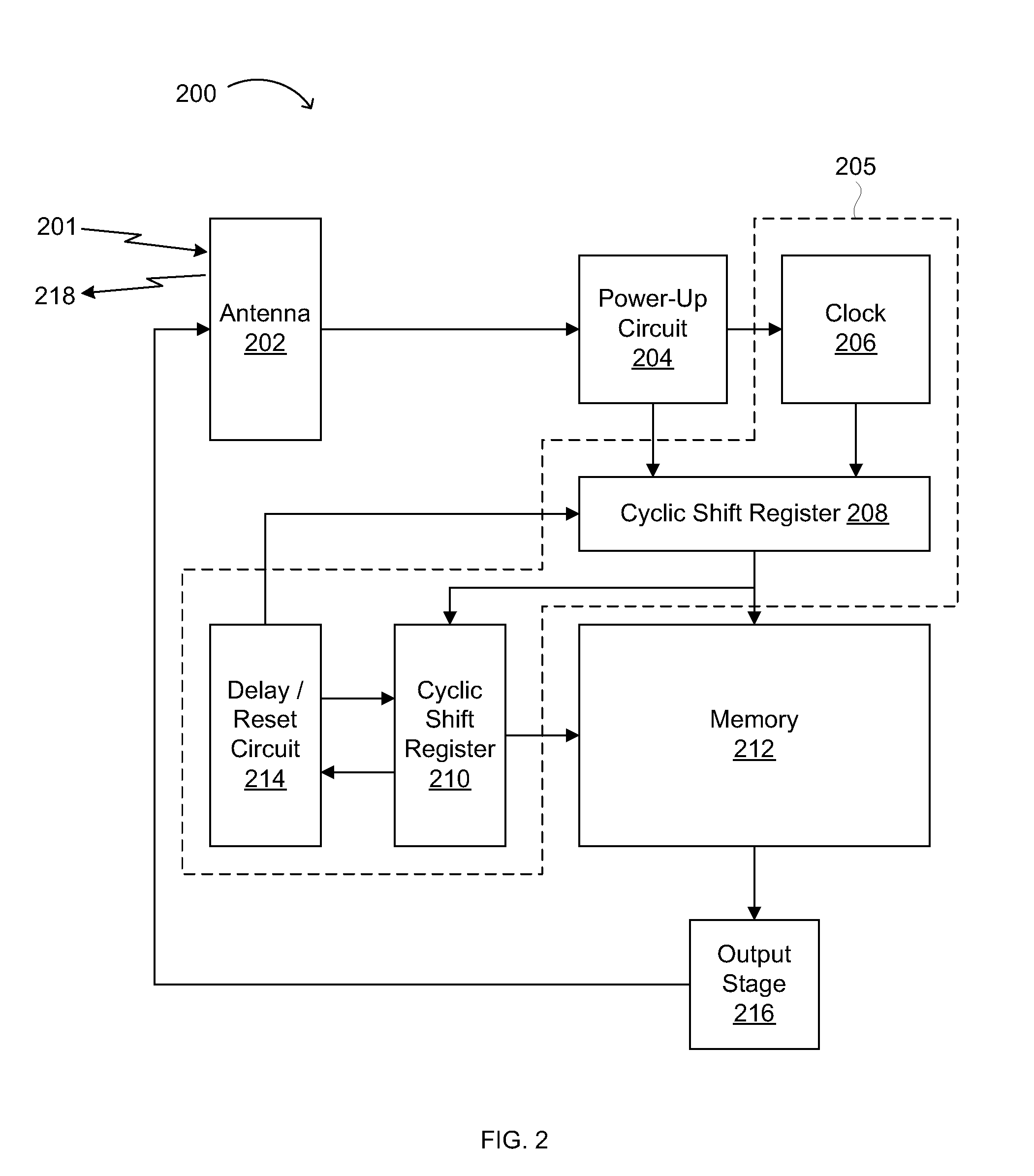
"The present invention provides a circuit for generating a delay using a delay element and a capacitor, as well as a thin-film field-effect transistor for providing a current or voltage to the capacitor. The current or voltage has a value that falls randomly within a predetermined range. This circuit can be used in a monostable oscillator for providing a repeating timing signal. The invention also provides a circuit for broadcasting a repetitive message in a wireless circuit, including an antenna, a power converting element, and a thin-film field-effect transistor for introducing a random delay in broadcasting the repetitive message. The invention also provides a method of forming a collision tolerant wireless system by determining a target variation range in the broadcast delay of wireless devices and making the wireless devices having the random variation range in their broadcast delay. The invention advantageously provides relatively low cost wireless devices with delay generating circuitry based on TFT technology."

Problems solved by technology

However, the complexity of circuitry which may be based on TFT technology is typically limited due to economic and technical reasons.
As a result, the number of transistors which may be available for implementing relatively complex circuit functions (e.g., conventional random delay generation circuits) is somewhat limited.

Method used


Image

  • Random Delay Generation for Thin-Film Transistor Based Circuits
  • Random Delay Generation for Thin-Film Transistor Based Circuits
  • Random Delay Generation for Thin-Film Transistor Based Circuits

Examples


Embodiment Construction

[0019]Reference will now be made in detail to the various embodiments of the invention, examples of which are illustrated in the accompanying drawings. While the invention will be described in conjunction with the following embodiments, it will be understood that the description is not intended to limit the invention to these embodiments. On the contrary, the invention is intended to cover alternatives, modifications and equivalents that may be included within the spirit and scope of the invention as defined by the appended claims. Furthermore, in the following detailed description, numerous specific details are set forth in order to provide a thorough understanding of the present invention. However, it will be readily apparent to one skilled in the art that the present invention may be practiced without these specific details. In other instances, well-known methods, procedures, components, and circuits have not been described in detail, so as not to unnecessarily obscure aspects of...


PUM


Abstract

Circuits and circuit elements configured to generate a random delay, a monostable oscillator, circuits configured to broadcasting repetitive messages wireless systems, and methods for forming such circuits, devices, and systems are disclosed. The present invention advantageously provides relatively low cost delay generating circuitry based on TFT technology in wireless electronics applications, particularly in RFID applications. Such novel, technically simplified, low cost TFT-based delay generating circuitry enables novel wireless circuits, devices and systems, and methods for producing such circuits, devices and systems.

Description

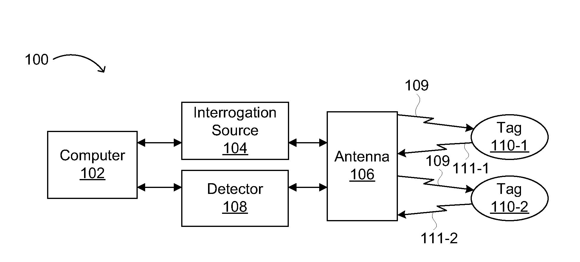
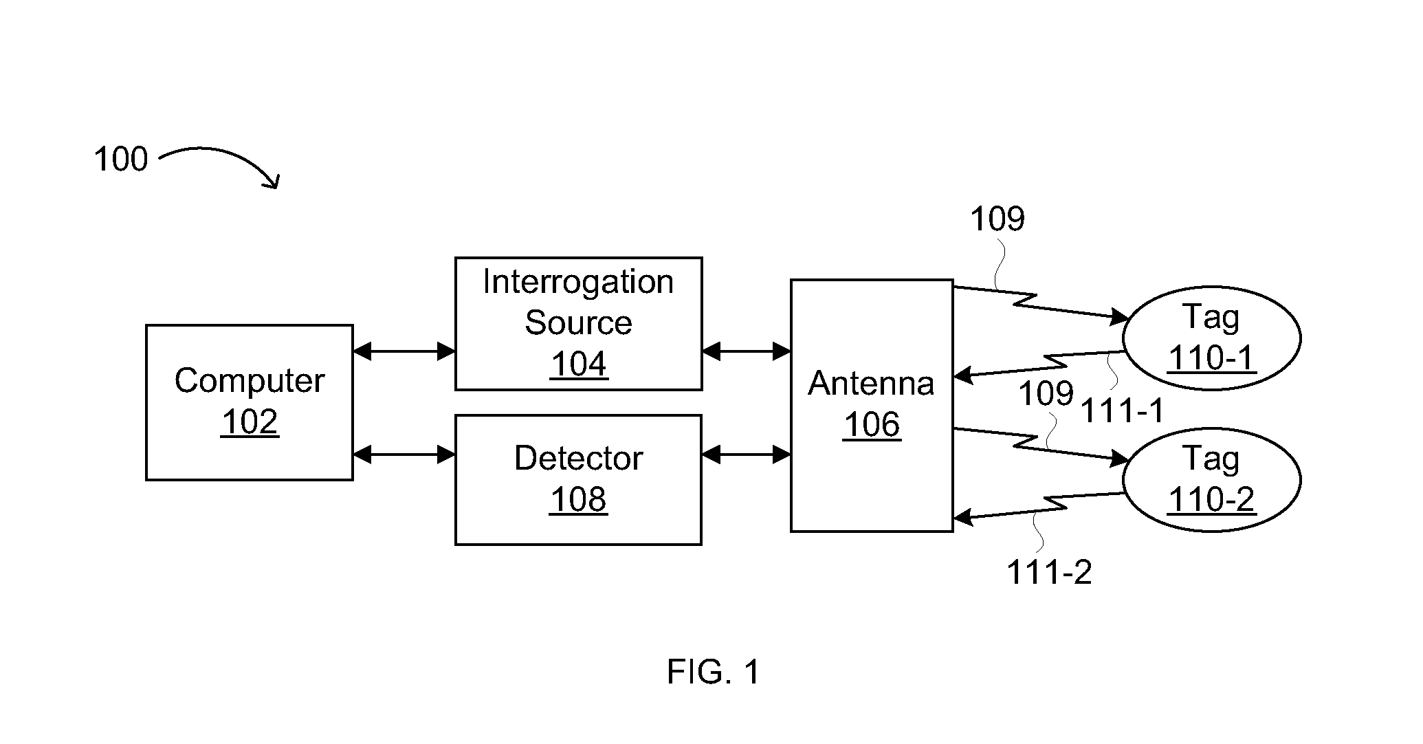
RELATED APPLICATIONS[0001]This application claims the benefit of U.S. Provisional Patent Application No. 61 / 118,184, filed Nov. 26, 2008 (Atty. Docket No. IDR2381), incorporated herein by reference in its entirety.FIELD OF THE INVENTION[0002]The present invention generally relates to the field of wireless communications circuits. More specifically, embodiments of the present invention pertain to circuits and circuit elements for generating random delay in wireless systems, circuits for broadcasting messages in low frequency (LF), high frequency (HF), very high frequency (VHF) and ultra-high frequency (UHF) and radio frequency identification (RFID) systems, tags and other devices containing such circuits, systems including such tags and devices, and methods for forming collision-tolerant wireless systems.DISCUSSION OF THE BACKGROUND[0003]Many communication circuits require random delay generators to arbitrate collisions between competing information streams. For example, FIG. 1 is a ...

Claims


Application Information

Patent Timeline
Patent Type & Authority Applications(United States)
IPC IPC(8): H04B7/24H04B1/04H03K3/36H03B5/12H04B5/48
CPCG06K7/0008G06K7/10059G06K19/0723H03K3/0315H03K5/13H03K5/133H01L2924/0002H03B5/1203H04B1/04H04H20/16H01L22/20H01L2924/00H03K3/033H03K3/355
Inventor SUBRAMANIAN, VIVEKMAO, MINGMINGWANG, ZHIGANG
Owner ENSURGE MICROPOWER ASA
Learn More